Introduction

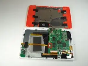
Use this guide in order to replace the motherboard within the Oregon Scientific Meep! X2.

  1. YLWlCTuGRDDQPWWN
    • Remove the orange covers from the left and right sides of the device by sliding up against the tabs.

  2. EKTkeNRLYujVD2lH
    EKTkeNRLYujVD2lH
    UNTb4RTP6ibquJ1q
    OINbQV1bQRDHKaBt
    • You can remove the rear casing by unscrewing all six phillips #00(3.5mm x 4.5mm)screws from the left and right side of the device.

  3. xspdyCQPa2kikpSH
    xspdyCQPa2kikpSH
    t6PXiSJbibeAiCfR
    TJZTOaOhPP4uv2iy
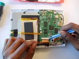
    • Use the plastic opening tools to undo the clips around the edges of the device.

  4. fpAwQpNU2bUJnWlv
    fpAwQpNU2bUJnWlv
    RULhRXqs6UDKTJoD
    OPeqeG4JtDTABnAW
    • Gently unhook the black security clips to loosen the ribbon cable. Use one of the plastic opening tools.

    • Pull lightly on the ribbon cable to remove it.

  5. MVM6fWPAQRsfZgfI
    MVM6fWPAQRsfZgfI
    46t6SOY4XwgeC5Yv
    • Use your spudger to separate the battery from the adhesive glue strips and plastic film.

  6. nQSucRmOXJKo1uiT
    nQSucRmOXJKo1uiT
    EnBiZ5PunHImrKrh
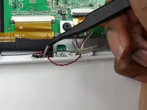
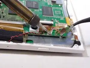
    • Use a soldering station to unsolder the battery wires from the motherboard.

    • In the case of screen or screen sensor replacement, disregard desoldering steps.

  7. LFvS1q5WHeZL2aFx
    LFvS1q5WHeZL2aFx
    XwrOWYOutphUMQNs
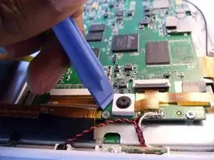
    • Slip the plastic opening tool under the white, square enclosure of the camera and lift upward to unhook the camera unit from the motherboard.

  8. cEaWEWyODBHYdlrR
    cEaWEWyODBHYdlrR
    NCUOGfdoDjJVyb2V
    • Pry the second camera out of its slot with one of the plastic opening tools.

    • Be sure to undo the black adhesive foam from the metal casing in order to remove the camera properly.

  9. T2NabQFEqLYS4CFs
    • Release the black security clip on the ribbon cable with your plastic opening tool.

    • Gently disconnect the gold ribbon cable from the motherboard. The two cameras will remain attached to the ribbon cable.

  10. Y5uKfGJAZKKupSAs
    Y5uKfGJAZKKupSAs
    HUfnJ3b4eIH1dXWC
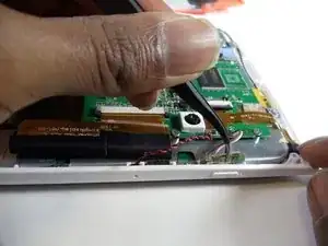
    • Use your tweezers to gently remove the microphone from the slot in the casing.

  11. ArvGsFYws6ScdAom
    ArvGsFYws6ScdAom
    SHGwuu6e1pRk6Ryc
    • Unsolder the microphone unit from the motherboard using the soldering station.

    • In the case of screen or screen sensor replacement, disregard desoldering steps.

  12. hBfNHkOLB6HJpJ1e
    hBfNHkOLB6HJpJ1e
    GLFZDqgytZVDRrjL
    • Use a tweezer to gently pull the power button sensor out of the case's slot.

  13. dd1MGYc5Ol4F1JyZ
    dd1MGYc5Ol4F1JyZ
    jALrbpJ1dRBkxNXO
    • Use the soldering station to unsolder and remove the power button from the motherboard.

    • In the case of screen or screen sensor replacement, disregard desoldering steps.

  14. 4aCMGD4mrgy3CZNe
    4aCMGD4mrgy3CZNe
    sAhilvGqqQ2SCru3
    • Undo the security clips on the ribbon cable connection by placing the plastic opening tool between the black and white parts of the clip. Pull downard toward the gold ribbon cable.

    • Once the left and right clips are undone, remove the gold ribbon cable from that connection by gently pulling it out.

  15. UbO3NXWvBCKY3sDN
    UbO3NXWvBCKY3sDN
    kQ4fEIaJCGeVC5bW
    • Remove the two phillips #00 (4.5mm x 3mm)screws located on the motherboard.

  16. 5uboYnMdKjSNCsxN
    5uboYnMdKjSNCsxN
    xZQRHWx4yGs6AUm1
    • Lift the silver, rectangular blocker in order to expose the right phillips screw #00 (4mm x 3.5mm).

    • Unscrew the left and right phillips #00 (4mm x 3.5mm)screws.

    • Once unscrewed, gently lift the motherboard from the rest of the device.

Conclusion

To reassemble your device, follow these instructions in reverse order.
J'mel Henneman

Member since: 20/01/15

864 Reputation

0 comments