Introduction
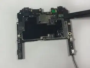
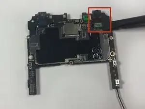
The Front Facing Camera is placed on the back side of the big motherboard chip. To remove the Front Facing Camera, the phone's motherboard needs to be completely removed.
Tools
-
-
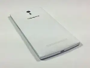
Turn the phone over so that you are facing the back side of the phone.
-
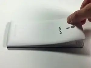
With your fingers, pry the back cover up starting from the top of the phone near the headphone jack and camera.
-
Completely remove the back cover by moving down the sides and bottom with your fingers.
-
-
-
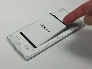
With your finger, remove the battery from the phone by gently lifting the top-right corner nearest to the camera.
-
-
-
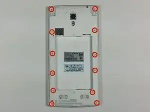
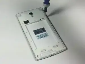
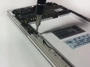
Remove the twelve exposed 3.6 mm Phillips screws on the rear of the phone using the 3.6 mm Phillips screwdriver.
-
-
-
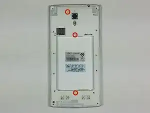
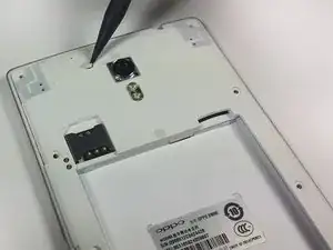
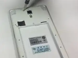
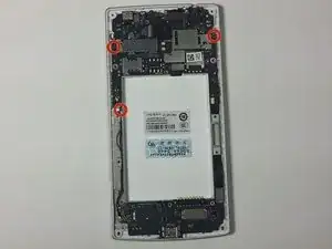
Remove the three circular rubber screw covers on the back of the phone by slipping the spudger into the border between the rubber cover and the chassis. In one motion, pry the stopper out of the hole. This can take some force.
-
-
-
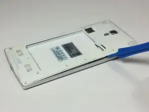
Insert the plastic opening tool underneath the chassis near the power button and pry the chassis from the phone. This should take a little force.
-
-
-
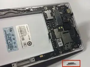
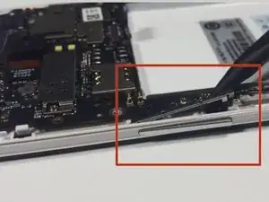
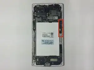
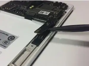
Use the sharp end of the spudger to pry the power button bracket from the side of the rear case.
-
-
-
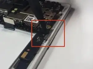
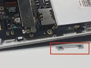
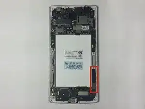
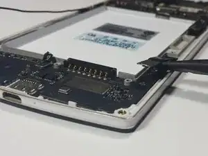
Use the sharp end of the spudger to pry the volume button bracket from the side of the rear case.
-
-
-
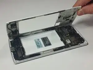
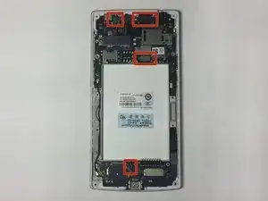
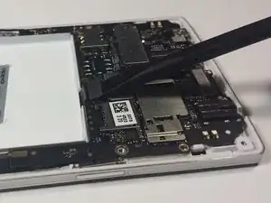
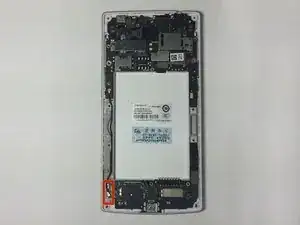
Using the flat end of the spudger, pry the four tape connectors straight up out of their respective motherboard sockets.
-
-
-
On the right side, there are two motherboard connections hidden underneath the motherboard. For these, insert the spudger in between the motherboard and the connection and rotate the spudger in a rocking motion until the two cables are disconnected from the motherboard.
-
-
-
On the bottom right only one connection is visible, however an additional connection is hidden underneath the first. To safely disconnect both, first unplug the visible connection then lift its tape up to expose the second socket. Similarly disconnect the second tape.
-
-
-
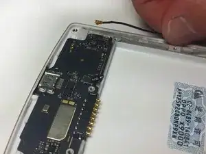
With your fingers, gently pull upwards on the WiFi antenna near the connection on the smaller motherboard until the antenna is no longer connected to the bottom motherboard.
-
-
-
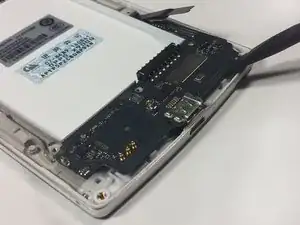
Use the spudger to carefully pry the small motherboard off of the phone.
-
Start from the sides of the lower motherboard closest to the charging port. Carefully pry the motherboard off until it is no longer connected to the phone.
-
-
-
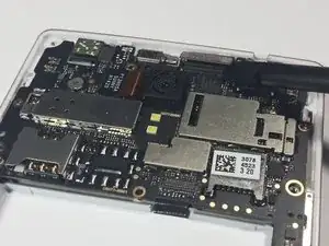
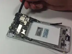
Use the spudger to carefully pry the bigger motherboard off of the phone.
-
Start from the top of the large motherboard. Carefully pry the motherboard off until it is no longer connected to the phone.
-
-
-
Turn the large motherboard chip around so that you are facing the back of the chip.
-
Use the flat end of the spudger to disconnect the cable that attaches the camera to the large motherboard chip.
-
To reassemble your device, follow these instructions in reverse order.
