Introduction

The guide will show you how to replace the micro USB charging port located on the bottom edge of the phone.

  1. h5ynssrkDIBplqRh
    h5ynssrkDIBplqRh
    YKMQVLJXCqIuPSJQ
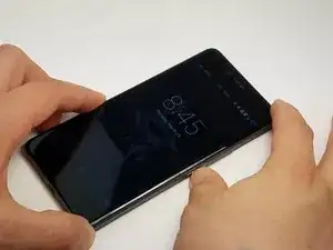
    • Power off the phone by pressing the button on the right side of the phone, it will be the smaller button.

    • Press and hold the button down for a few seconds, until the option "Power Off" appears on the screen.

    • Select "Power Off" on the screen to turn off the phone.

  2. L2e5qBKbogbIsUd4
    L2e5qBKbogbIsUd4
    e1IwERvEbMF4kmKF
    KNwuu4XIgVyKg1wP
    • Insert a SIM card removal tool into the small hole located on the top right corner of the phone, just above the volume buttons.

    • If you do not have the original packaging or a SIM card removal tool, you may use a straightened out paperclip or something similar.

    • Push the removal tool into the hole and the tray should pop out.

    • Remove the SIM tray from the phone.

    There is absolutely no reason to remove the sim tray, we're not removing the motherboard.

    Dennis Meerveld -

    You could at least save your SIM cards (and uSD card) some of the unnecessary heat treatment that way.

    S K -

  3. SYaDa1iqd2QjvDVL
    SYaDa1iqd2QjvDVL
    Y1hfpUJeNAN6muGo
    sPJPHMo2QQbPqIa2
    • Put on heat-resistant gloves and place the phone on a surface that will not catch fire or melt.

    • Using a heat gun, apply slow and even heat to the edges of the back panel.

    • DO NOT stay on one spot for too long, the heat gun can damage the phone if the heat is applied to the same area for a long period of time.

    • While heating the back panel, use a Jimmy to test if the adhesive is soft enough to allow the panel to separate from the device.

    • Carefully detach the back panel, using opening picks to hold the panel apart from the device.

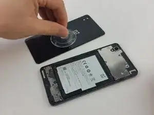
    • Once most of the edges are separated from the device, attach a suction cup to the back panel.

  4. xFJXCTP4OmExHHDQ
    xFJXCTP4OmExHHDQ
    GJxEsbXs2Q1nc5E4
    gUBkCDuyaddfrrf3
    • Press the suction cup to the back panel to secure it.

    • With the help of the suction cup, pull up on the panel to completely detach it from the device.

    • Use the suction cup to safely remove the panel from the device. As you work around the panel's edges, the lingering heat may cause the remaining adhesive to reattach the panel to the device, be sure to lift the back panel before the glue has time to set back.

    It can't be stressed enough to do this very carefully. I did it very carefully, but not carefully enough. Cracked a corner. Also not just the edges, there's extra adhesive on the lower 2-3 cm's of the back.

    Another remark, get in between the black bezel and the back cover, this is a bit unclear on the first picture. Same goes for the front, get in between the bezel and the front assembly.

    Dennis Meerveld -

    Most of the adhesive is on the top and bottom ends, yes.

    I would recommend one to steer clear of the camera assembly though (the LED lens is plastic and melts) + the center (where the battery is, mine swelled a bit).

    S K -

  5. DWbKZI4ntppac4P2
    DWbKZI4ntppac4P2
    oxXkYDUU3yQWaoLb
    gFI55jsX3Z5ZrlaI
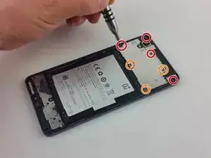
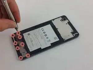
    • Using a PH000 screwdriver, remove the following seven screws circled with red and orange:

    • Four (longer) PH000 screws

    • Three shorter PH000 screws

    • Once all of the screws are removed, proceed to using a plastic spudger to pry the metal cover off.

    • There are two clips near the bottom, right above the battery, so start by prying on the bottom edge of the plate.

    What size of screw goes where?

    Will -

    Check http://imgur.com/wqD9Dis. Orange circles are the smaller screws (3 out of 7 are smaller than the other 4).

    Dennis Meerveld -

  6. uqBG3p4pVuLVS1Nw
    uqBG3p4pVuLVS1Nw
    MdPFnJIrgCjPreRA
    • Once the metal cover is removed, locate the battery connector wire, which clips into the motherboard.

    • Using a plastic spudger, gently pry on the clip to release it.

    • This will cut power to the phone, and prevent any power running to any of the components which is important while working on the phone.

  7. 6JMGGr6ExXkbNIOT
    6JMGGr6ExXkbNIOT
    Kpy6q4E4EsgbhNKU
    XjIb5Qpc1XySMZYb
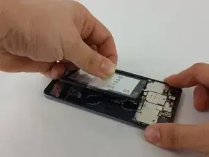
    • On the battery, locate a clear tab. This will be used to pull the battery out.

    • Firmly grasp the clear tab and pull up and away from the phone to remove the battery.

    • Take your time during this step, as you do not want to apply too much force and damage the battery.

    • There is an adhesive underneath the battery so it might be useful to utilize the black plastic spudger to get between the battery and the phone to pry the battery up but be very careful not to break the ribbon cables underneath the battery.

    • Continue to pull slowly on the battery, until it is completely free from the phone.

    Strictly speaking, you don't need to remove the battery at all. The connector to the front assembly is underneath the speaker assembly.

    Dennis Meerveld -

    If your order the complete part you need to remove it.

    The battery is glued in very well and it bends pretty easy. It is wise to order a new battery aswell.

    Chris S. -

    I agree it's nearly impossible to remove the battery without damaging it. Even a tiny little bending can lower the capacity. And if you heat it up too much to soften the glue it can explode. Also never use metal tools on the battery in case u break through the protection foil it won't catch fire.

    Peerless Records -

    The instructions on the pull tab itself are pretty clear and contradict what's said here!

    "Tear from position 1, and then pull out the battery from position 2."


    The battery sits in a kind of a black "vest", which is the thing glued to the phone (not the battery itself).

    This vest can be "unbuttoned" from the top and bottom sides (position 1, visible on some of the previous pictures).

    After that the battery would pop out with much less effort (there is some adhesive in the "vest", but it's much less robust).


    What is being depicted here is quite dangerous and unnecessary, as it makes the battery bend heavily.

    S K -

  8. TebQJGbcUMLSLUu2
    TebQJGbcUMLSLUu2
    bV2FoVEkJXWEFhug
    • Using a PH #000 screwdriver, remove the 8 screws from the motherboard, circled red in the diagram.

    • As long as the screws have been removed prior to removing any cables or wires, the order in which you remove the screws does not matter.

    • Once all the screws have been removed, use the plastic spudger to pry the metal cover off.

    • The metal cover will be a little difficult to pry off due to adhesive, make sure not to apply too much pressure.

    The four screws on the bottom are the long ones. The four near the battery are the shorter screws

    Chris S. -

  9. OKo1cVTyq2gLTj4I
    OKo1cVTyq2gLTj4I
    aguclcS5ObQKos1c
    wxEypNLM3wxEF2Nh
    • With the battery removed and the metal covers off, disassembly can continue.

    • Using the plastic spudger, locate the rear-facing camera and unclip it. Once unclipped, set the camera aside.

    • Using the spudger, pull off the wire connector, circled red in the diagram, and push it away.

    • Make sure to have pushed away any cables or wire connectors before removing the upper motherboard.

  10. WyFN1sfNY1WgFZwl
    WyFN1sfNY1WgFZwl
    iKtPE5NqoF6NyBXI
    YPyC3RLgVGRrJdKG
    • Using the plastic opening tool pry the upper motherboard. Carefully pry it up until you can safely remove the upper motherboard completely.

    • Be careful when pulling up the upper motherboard, the front camera is clipped underneath and pulling too hard may damage it.

    • On the bottom left hand side of the phone, you will see a small screw. Use the PH #000 to remove that screw.

    Switch back to the plastic spudger and start to pry at the upper logic board. Carefully pry it up until you can safely remove completely.

    This should not been done from the top but from the bottom, just as the metal cover from step one.

    And before starting, make sure the three state button is in the top position.

    local host -

  11. GvOvu2ALGZ4BwrcT
    GvOvu2ALGZ4BwrcT
    yC3kfOKM3yu5FdVW
    iKcdsnnE2xZGfnJ4
    • After removing the Phillips head screw, you will need to remove a black wire. Use a spudger to unclip the cable first.

    • It might be helpful to bend the cable out of the way when working on the phone.

    • Pull back on the ribbon-cable as shown in the image. This is connected to both the charging port and the vibration module (which is similar to a small watch battery).

    • Gently pry the vibration module out with a plastic opening tool. Be gentle, for it is adhered to the phone.

    • You will need to remove the vibration module before the charging port.

  12. 6fE4qEAB1QBClKTR
    6fE4qEAB1QBClKTR
    LCvUuOxVkSPFPckD
    XsJjJaFaRJOqhEHI
    • Once the vibration module is out, pull up carefully on the cable as the charging port is attached with adhesive.

    • After carefully pulling the port and vibration module, it should now be free from the phone and can be replaced.

Conclusion

To reassemble your device, follow these instructions in reverse order.

Luis Castro

Member since: 08/02/16

2061 Reputation

7 comments

So how do you replace the part with a new one? Says in the top description "no parts required"

Robin -

I had to reuse the vibration motor de- and solder it back on, because it is not included in the spare part.

Watch for the silence switch when you reasamble the phone. I had to unscrew the upper bord again because i didn't payed atention to it and it was locked. Also the mic is covered on the replacement part. Don't forget to remove the yellow "flag" there.

OxKing -

I replaced USB flex port, now working, but now phone dont recognize SIM card..what i must check? Thanks for any help

superlerry -

What is the price of charging port with vibrator module
santhosh gowda -

Good Instructions

In the upper right Corner is one more Screw

where the Logic-board is screwed directly.

That was not mentioned!

Also, you should pay attention that you do not pry where the PCP goes around the Camera.

I break off the Corner, fortunately it's only connected to the Status-LED.

Otherwise everything works.

Tesla Toni -

Thank for the instructions, this came in very handy!

I agree with all the above remarks:

- The screw in the upper right corner

- Battery comes out difficult, but you can listen the sealant come loose, so don’t force it!

- As well, don’t pry to much on the logic board, it’s being hold down by little ‘clips’ on the phone edge. Gently ply the edge toward the outside and it will click loose.

After reinstalling everything, all works perfectly! (saving me a lot of money !)

Thank you!

plessers_bart -

i did not try this out, since everything is ok with my phone (I was looking for polarity of the contacts of the battery connector actually), but this instructions seem very weird to me (as they are now): if you want to change the micro USB port, WHY on earth would you have to remove the logic board??? they are on opposing sides of the device and connected with a flex-cable, I don’t see the necessity.

Max -