Introduction

This guide is designed to teach an ifixit user to replace the sensor lens for an Olympus E-PL1 camera.

  1. 5S43IkhAEjfIAuIQ
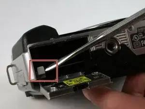
    • Push the gray tab down, using a spudger if necessary, and the battery will come out.

    • Failure to remove the battery prior to disassembly can result in harm.

  2. 5HEMeqWFUrlIfiLl
    5HEMeqWFUrlIfiLl
    Sy2HZRDaDXZTFUC6
    Xk2bikRbFAwSSYKl
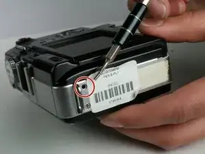
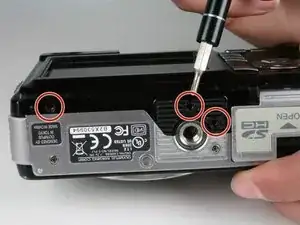
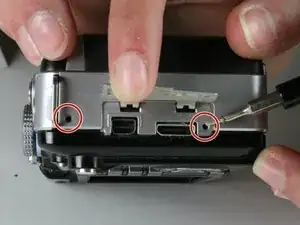
    • There are a total of six screws that must be removed using the the #000 Philips screwdriver.

    • As per picture one: there is one 4.9 mm Philips head screw on the left side of the camera.

    • As per picture two: on the bottom of the camera, there are three 3.4 mm Philips head screws; these are located on the darker area of the case.

    • As per picture three: there are two 5.3 mm Philips head screws on the right side, one is beneath the USB cover.

    Does this method can be applied on Olympus Pen E-P1 Model? Do you have a tutorial like this on that said model I’ve mentioned?

    Matt M -

  3. kWBBCK33yZ6GZnq1
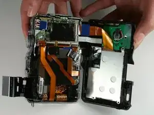
    • Open the case by peeling off the back panel.

    • Pull the case apart gently so that the ribbon connector will not tear.

  4. UpCFtwRfCQsxP5t5
    UpCFtwRfCQsxP5t5
    dphkrwOaWdK3quPT
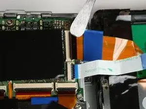
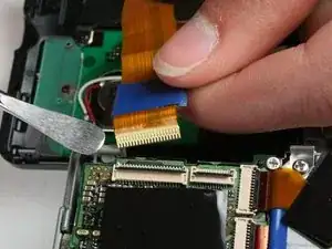
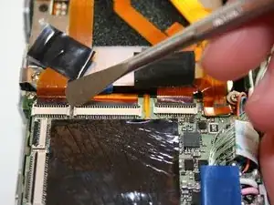
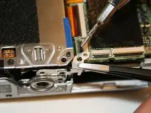
    • Disconnect the two ribbon cables as shown in picture one.

    • Avoid using metal pry tools, as shown in the photo, on internal electronic components, as it can cause a short and damage the device. Use an ESD-safe tool such as a standard nylon spudger.

    • To disconnect a ribbon cable, use a spudger to lift the black tab then pull the ribbon out. This works the same for all ribbon cables.

    The cables (2) on the camera back are quite short. Because of this, removal is quite easy while reconnecting can be challenging. You might have an easier time if you use some masking tape connecting the back to the front loosely to support the back as it takes both hands to reconnect the cables.

    davel4wa -

  5. nSLRJXAPyFS2rUlp
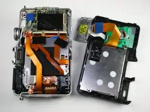
    • The back panel has now been removed.

  6. DRARAQFk2AZS6VB2
    DRARAQFk2AZS6VB2
    vLrRMG1PrxfNsDUh
    aFFrBigkeDwcAhnn
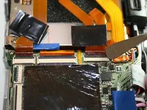
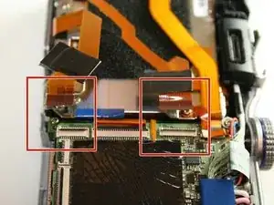
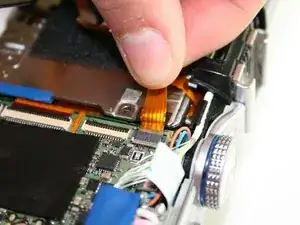
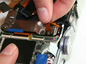
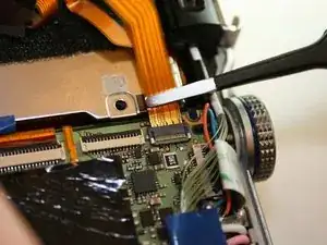
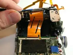
    • Using a spudger, remove the ribbon cables by pushing the black tab back and gently pulling the cable out.

    • Avoid using metal pry tools, as shown in the photo, on internal electronic components, as it can cause a short and damage the device. Use an ESD-safe tool such as a standard nylon spudger.

    • Do this process for the two ribbon cables shown in the third photo.

  7. RYMqkGQtdN2I5ITO
    RYMqkGQtdN2I5ITO
    tGnDpaTycm12eRHE
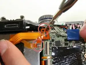
    • Using the #000 Phillips screwdriver, remove the 4.3 mm screw as shown by the screwdriver and the 6.0 mm screw holding down the ribbon.

    • These screws have washers on them, do not to lose them.

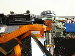
    • Using tweezers, gently lift the ribbon off the sticky pad.

  8. nrsSCMwSiadZJfaF
    nrsSCMwSiadZJfaF
    ICxwHCVIGvjxCTLp
    ZcsSm3odGUWUGa62
    • Unlike previous connectors, this cable has a light grey clip holding it in place on opposite side of the connector in regards where the ribbon is inserted. Flip it up and then using your fingers, gently pull the top ribbon cable out.

    Flip up the grey lid opposite the cable and then gently pull it out

    Heiner Sommer -

  9. UmmXsKjdAceT4qAA
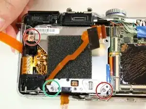
    • Using a #000 Phillips screwdriver, remove the 6.0 mm screw on the bottom left hand corner. You can locate the screw on the picture as the green circle.

  10. wWCQ1R4IoZjsTNx6
    wWCQ1R4IoZjsTNx6
    FkfjGDYnLXe3W4GF
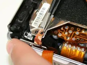
    • In the upper left hand corner, use the #000 Phillips screwdriver to remove the 6.0 mm screw.

    • Retain the copper washer held in by this screw.

    • Using tweezers gently lift the copper grounding strip.

    • Do not tear the strip as you pull it off, it must stay attached to the main camera body.

  11. G1LZhoU4HBZQnMgK
    G1LZhoU4HBZQnMgK
    UskJLtELJ6SjERjX
    yaUkUWslU4mQQKHC
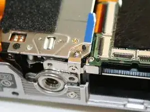
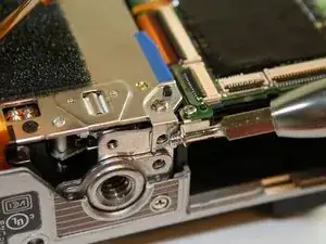
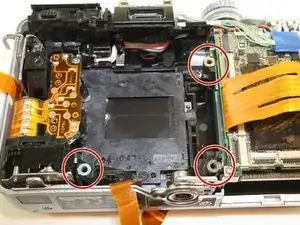
    • Remove the bracket in the lower right hand corner. In order to do so, you must remove two different screws.

    • Using the #000 Phillips screwdriver, remove the 2.4 mm screw on the bottom.

    • Using the #000 Phillips screwdriver, remove the 6.0 mm screw on the top and lift off the bracket.

  12. qjDPCBCTc4OQPEq4
    qjDPCBCTc4OQPEq4
    LEyKZBevpxTiTdFL
    ySoxNZUOJVoXHXTB
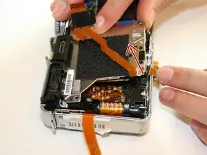
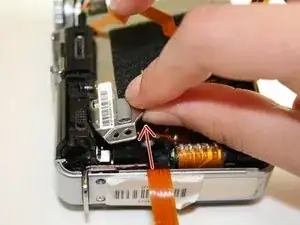
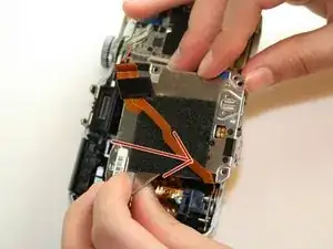
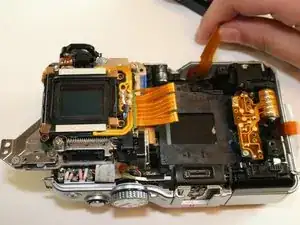
    • Now you can lift out the sensor assembly. The following steps will explain how to lift it out.

    • First, sightly lift the bottom half following the direction of the arrow.

    • Second, lift the top left up side up. It may be a little stuck so you will have to wiggle it out.

    • Finally, pull the entire assembly towards the bottom and away from the case.

    • There is a ribbon connector that is beneath the assembly. Be careful when lifting the assembly out. Do not yank it out very hard or you may damage the ribbon connector.

  13. mfbW1CYvU2D3ZlOE
    mfbW1CYvU2D3ZlOE
    uDFogT2uyCWKZHTA
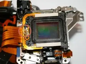
    • This is the sensor assembly with the photo showing the connected ribbon cable.

    • There are three washers held in by the 6.0 mm screws as shown in picture two. Be sure to replace them when reassembling.

    after removing sensor assembly, besides these three washers I found three more. Where could they come from?

    kantora98 -

    All the washers come from underneath the 6 mm screws. I had 8 washers alltogether. Allways two together.

    Heiner Sommer -

    I have six (6) washers as well. Three (3) have black marking, two (2) have green marking, and one (1) has purple marking. If there are multiple washers per position I would need two more. I measured the thickness of each one thinking that they are shims to correct the sensor to be parallel to the shutter. If so, the colors on each one don't coincide with a particular thickness. Perhaps the color identifies a position of one of the four mounting bosses, then there are only three colors for four bosses. Perhaps one boss had no washer at all. In any case, it is unlikely the sensor will be back as it was since all but one washer was found lying in the underlying area.

    davel4wa -

  14. wDpMMaxs5YE4MALH
    • The sensor assembly has been removed.

  15. CtTDUy2Vuuw31A3m
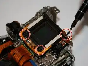
    • Remove the 3 screws surrounding the sensor lens with a #000 Phillips screwdriver.

  16. hUOQbYth3rSYKl6Y
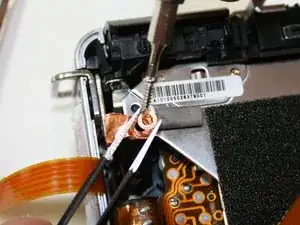
    • Using a soldering iron and soldering wick desolder the two wires connecting the lens.

    • take note of the colors of the wire as the new lens must be attached in the same manner.

    • Solder in the new lens. Be sure to match the wire color to the original wire placement.

  17. EHbyqMBm5EABF5lF
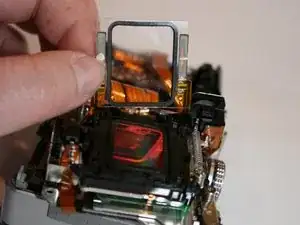
    • Remove the sensor lens by pulling back as shown.

Conclusion

To reassemble your device, follow these instructions in reverse order.

Jeffery Smith

Member since: 11/03/15

748 Reputation

One comment

Hello. Is it possible to remove glass from sensor without damaging microwires? I want to debayer sensor.
Gediminas Jesinas -