Introduction

This guide is used for the replacement of the Rumble Modules on your Nintendo Switch Pro Controller. Take precaution when completing this guide because it involves the removal of a lithium-ion battery. If the battery is swollen, check out this resource on how to dispose of a swollen battery. To complete this guide correctly you must complete steps eight and nine with caution so as to not damage the white ribbon. In addition, you must be able to solder, so if you do not know how to solder, check out this resource on how to solder. Be careful when removing the plastic pieces and the internal circuit board of the controller so as to not damage the components.

  1. iaKRfcPV2HNC5yUK
    • Flip the controller over so the model stickers face the ceiling.

    • Use a JIS #00 screwdriver to remove the two black 8.4 mm screws that secure the handles, located at the ends of the handles.

    Be carefull, these screws are super easy to strip even with the right tools.

    Lukas Eberharter -

    I tried editing these instructions after I had trouble with stripping screws, but it doesn't seem to take. The issue is that these are JIS and not Phillips screws. They are VERY similar looking but a Phillips head screwdriver will strip the screws.

    Isaac Webb -

    I tried using a Philips #00 screwdriver but it didn’t work

    vincent ingrassia -

  2. pFHHOlTyvlQ43DOC
    pFHHOlTyvlQ43DOC
    KCE54LsPyGnuWTkW
    UNYZtREEKVfHallZ
    • Carefully remove the handle covers by pulling them away from the main body.

  3. 3OnYDcOU1gVR2fEG
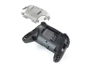
    • Use a JIS #00 screwdriver to remove the four silver 6.8 mm screws that secure the clear back plastic cover.

  4. Zb3Ool4Evh63KKVd
    Zb3Ool4Evh63KKVd
    E4qBEgOibCQbXlIJ
    jihxJQfDSqclVJnF
    • Carefully pry away the clear plastic cover using your fingernail.

  5. p4bHAkTpIvuBFIfc
    • Remove the clear plastic cover.

  6. yUbMYllrTC6sSOGL
    yUbMYllrTC6sSOGL
    6pxWhyQpxoXGbs22
    vEF6WXIGCHUebiZO
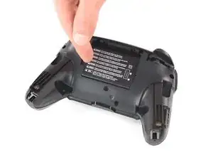
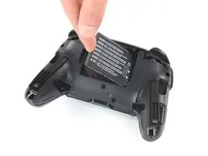
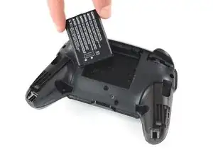
    • Remove the lithium-ion battery by using a fingernail or plastic opening tool to pry it up on the left side.

    • Only a small amount of force is needed.

  7. V5kF4MuHympJyAFM
    V5kF4MuHympJyAFM
    WJ4LvGQlKLhlREns
    IhtOVVcrnx5IBHgJ
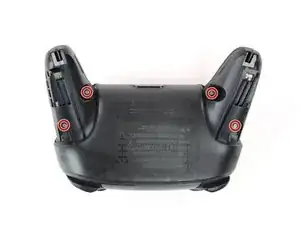
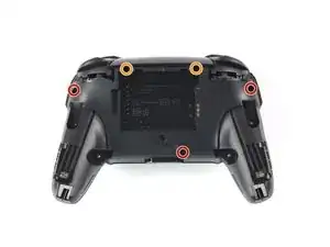
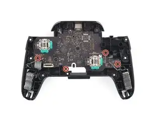
    • Use a Phillips #1 screwdriver to remove the five 5 mm screws from the back of the controller.

    • The two case screws above the handgrips and the single case screw below the battery bay have a shallow seat. These three screws can be easily removed.

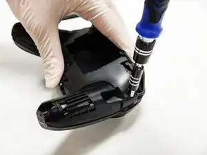
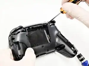
    • The two case screws adjacent to the ZR and ZL shoulder buttons have a deep seat. Use an extension or a Phillips screwdriver with a longer shaft to reach these screws.

    the 2 screws up at the top are unreachable with the standard fixit kit just a heads up

    drew -

    Seconded. the screws are located too deep below the plastic slot, and the bit holding bulge is too wide for the small aperture (similarly with the flexible extension). the bit length is too shallow to reach.

    An alternative driver with a much narrower & longer shaft is required, which will likely not come with interchangeable bits.

    Douglas Selby -

    I would say it is possible to reach the top left screw, just not the top right - there is a gap in the top left that allows you to slightly bend the standard driver outward to turn it while still making adequate contact.

    El_Mechacontext -

    An update: I was actually able to remove the top right one in a really hacky way - inserting the Phillips #0 bit into the #4 hex bit, and then using that in the standard driver. This added just enough length to successfully reach and make full contact with the screw!

    El_Mechacontext -

    Using the #4 hex bit as an extension was the exact "hack" I needed to get rid of the drift finally. Thank you. You're a lifesaver.

    Das #4 Hex Bit als Verlängerung für das Kreuzschlitz Bit zu nutzen ist zwar etwas eng, aber es erspart einem wirklich einen zusätzlichen Schraubendreher.

    Techn0magier -

  8. PnIrdtdY4KCyxuKK
    PnIrdtdY4KCyxuKK
    ZBKtxPXnhQuBTaDN
    OZcevYGCPPARFaRx
    • Delicately take off the plastic cover from the controller.

    • Do not completely remove the front cover just yet, as it is still attached to the motherboard via a white ribbon cable.

    Didn't realize there is adhesive holding the front cover onto the unit. It's located inside of the handles. Just a bit of force there helped, just be careful of the cable.

    Roger Perez -

    this step is really hard

    XDchlapec -

  9. NpVhXDsYSWmW4tBT
    NpVhXDsYSWmW4tBT
    QXe1DlCMuCXbrveX
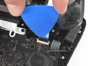
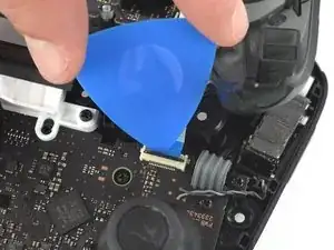
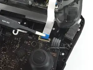
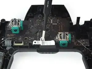
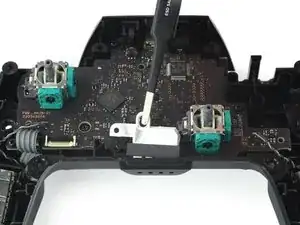
    • Use the tip of an opening pick to open the black flap of the ZIF connector by pushing it upwards.

    Having just completed this repair, I noted that this ribbon cable can disconnect on either side. It is easier to disconnect and reconnect from the other side than what is shown in my experience.

    acestronautical -

    @acestronautical is right! much easier to remove the ribbon cable from the button board, connect to the base board and then connect back to the button board. Thank you @acestronautical

    Joe Rickerby -

  10. 3qj6VtFJtKAHHm6I
    3qj6VtFJtKAHHm6I
    YJvaLXngDhvHF1Gr
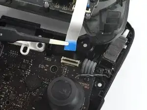
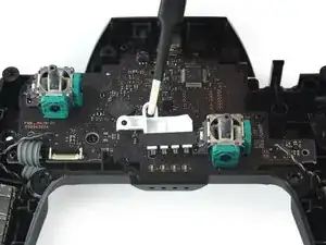
    • Use your fingers or a pair of blunt nose tweezers to disconnect the interconnect cable from its connector.

    You don't need to disconnect this as long as you are fine with keeping it close by so as not to rip the ribbon cable.

    Caden Helm -

  11. OpC2vBHXBB35uAQ4
    • Remove the front case.

  12. fmhalkYPurcsCRYL
    fmhalkYPurcsCRYL
    elaYKLLtkDSyGABw
    rEIOPXEXhFo3sEO1
    • With light force pull the two joystick caps off of the controller.

  13. HpPnoTw2oVU5odHN
    HpPnoTw2oVU5odHN
    pBBnnW3FYeTkDTo4
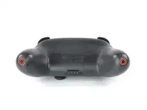
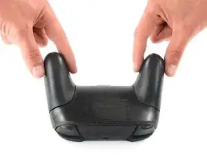
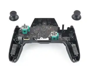
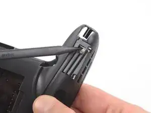
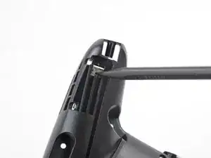
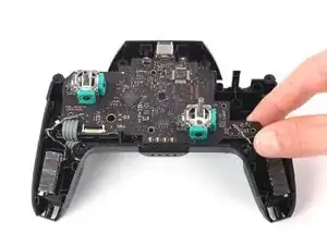
    • Insert the tip of a spudger from the back into the hole on the right controller handle.

    • Push the spudger through the hole to loosen the adhesive which is holding rumble modules in their places.

  14. ywrKJmgVYNUGlrUM
    ywrKJmgVYNUGlrUM
    BISvKHpMS1DNiXYW
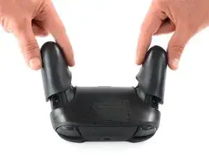
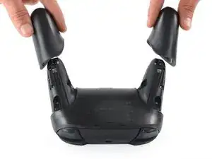
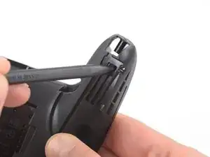
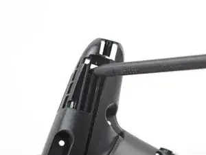
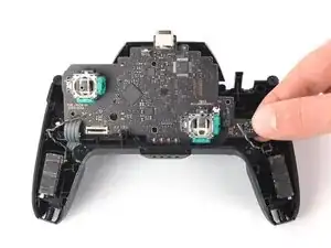
    • Insert the tip of a spudger from the back into the hole on the left controller handle.

    • Push the spudger through the hole to loosen the adhesive which is holding rumble modules in their places.

  15. pSXEQWgJfaVMvFBE
    pSXEQWgJfaVMvFBE
    eGaKJXVbGkns5qSd
    • Use a pair tweezers to lift the modules out of their places.

  16. mPwXoXbItirFTqAd
    • Use a Phillips screwdriver to remove the four 5 mm-long screws securing the motherboard.

  17. DkHZNPYKTFgGGwQj
    DkHZNPYKTFgGGwQj
    rdqd3X5NWRvfAASb
    mjhakMjwswRNykjv
    • Use your thumb or a pair of tweezers to to take off the white LED light housing.

  18. NjOknKYPoSaynVej
    NjOknKYPoSaynVej
    yk6VDfhaUbXCxAKg
    eJTHvLHbRrQqKjIC
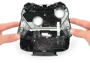
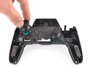
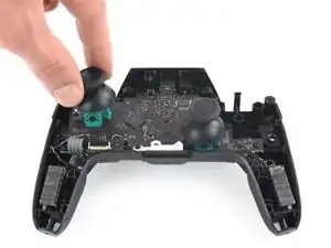
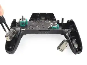
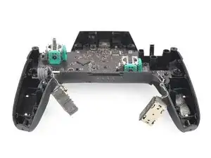
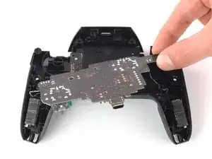
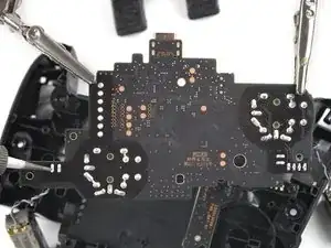
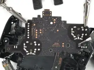
    • Lift the motherboard carefully as to not damage the wires and flip it to reveal the backside.

  19. jsM6bSetmHAUvnrX
    jsM6bSetmHAUvnrX
    BKEhDG2Dpey1MUgQ
    iaJsCB6DwLfg6mjT
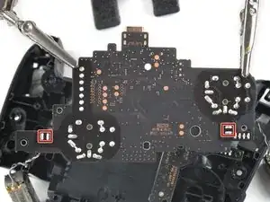
    • Desolder the rumble motor solder points on either side of the motherboard.

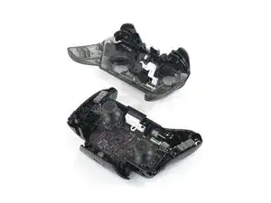
    • Remove the rumble modules.

    • Refer to the following solder guide if necessary: How to Solder

    • Solder the new rumble modules into the same pins.

Conclusion

To reassemble your device, follow these instructions in reverse order.

Jean Galindez

Member since: 16/09/20

706 Reputation

One comment

Is the controller operational if I just leave the rumble module de-soldered?

amp -