Introduction
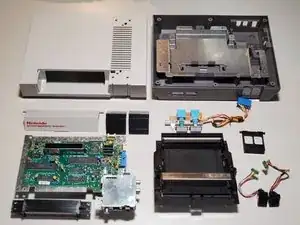
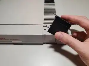
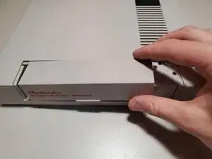
Disassembly of the NES. Use this guide to learn how to open the system and replace items such as the 72-pin connector, controller ports/buttons, & plastics.
-
-
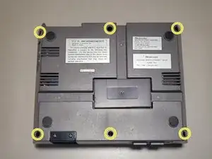
Remove six 13.25mm Phillips screws on the bottom of the system.
-
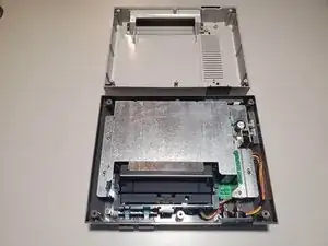
Once all screws are removed, simply lift the bottom half away from the top housing.
-
-
-
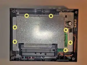
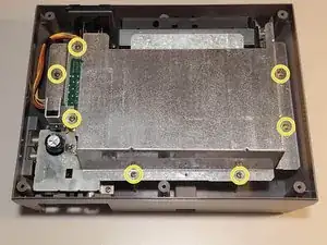
Remove seven 13.25mm Phillips screws around the perimeter of the RF shield.
-
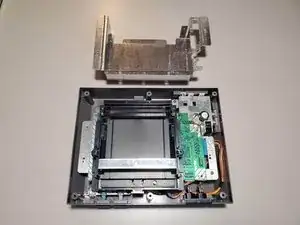
Lift the RF shield up and away from the system and place aside.
-
-
-
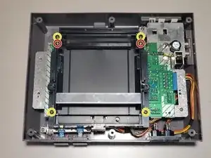
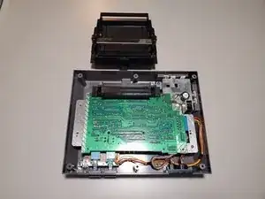
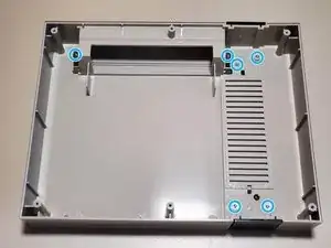
Remove four 13.25mm Phillips screws from the four corners of the cartridge tray.
-
Remove two 17.25mm Phillips screws from the top of cartridge tray.
-
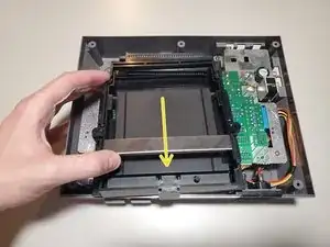
Once free, slide the cartridge tray towards you and then lift slightly in the front to remove.
-
-
-
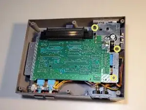
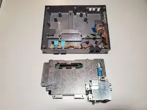
Remove three 13.25mm Phillips screws to free the motherboard from the bottom housing.
-
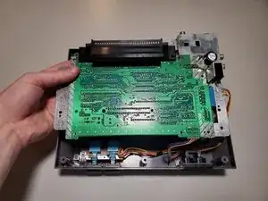
Carefully lift the motherboard and turn it over to find the wired connections.
-
-
-
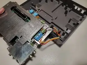
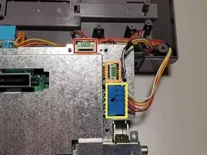
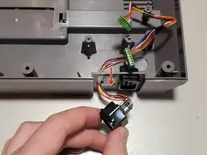
Disconnect the wired connections from the motherboard.
-
Player 1 (Shorter wires)
-
Player 2 (Longer wires)
-
Power/Reset Buttons
-
-
-
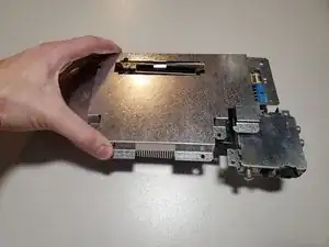
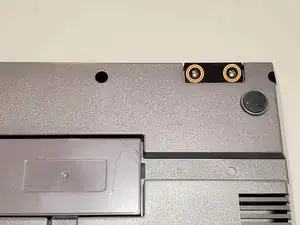
The bottom RF shield is held on by tension around the expansion port. Lift the shield up and away from the motherboard.
-
-
-
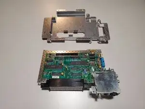
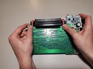
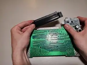
To remove the 72-Pin connector, apply force to each edge and slide the connector off the contacts on the motherboard.
-
-
-
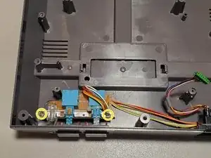
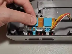
Remove two 13.25mm Phillips screws from the button assembly. Lift slightly in the back and then up and away from the housing to remove.
-
-
-
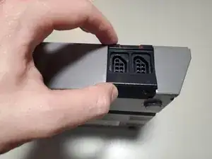
Remove two 7.25mm Phillips screws from the bottom of the system. Lift the controller port faceplate up and away.
-
Remove the controller ports by feeding them through the port holes to the front of the housing.
-
-
-
Remove seven 7.25mm small flathead screws from the inside of the top housing.
-
Two of these screws also hold a spring for the door. When reassembling, refer to the keyed shape of the plastic to orient these correctly.
-
-
-
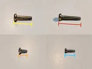
Screw List
-
(19x) 13.25mm Phillips
-
(2x) 17.25mm Phillips
-
(2x) 7.25mm Phillips (Silver, large cap)
-
(7x) 7.25mm Flathead (Silver, small)
-

To reassemble your device, follow these instructions in reverse order.