Introduction

Use this guide to replace the trigger buttons along with the SD card board cable.

  1. xvUu2VHXnLOaoxyD
    xvUu2VHXnLOaoxyD
    GJgBKkUY2j6UrTTr
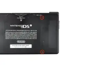
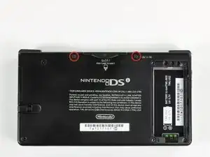
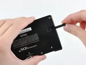
    • Unscrew the two Phillips screws securing the battery cover to the lower case.

    • The screws remain captive to the battery cover.

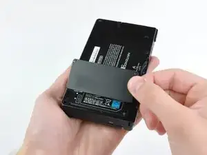
    • Grasp the battery cover and lift it out of the lower case.

    • If it's difficult to grasp, lightly tap the opposite side of the device.

  2. TMGAeGDWRXJKjqkf
    TMGAeGDWRXJKjqkf
    pXTJP3k1hRhVckSv
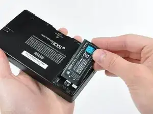
    • Using a spudger tool (or your fingernail), lift up the battery from the top.

    • The liquid damage indicator sits underneath the battery. Pry gently, or you may damage the indicator.

    • There's a small tab on the top of the battery to make removal easier.

    • Grasp the battery and remove it from the DSi.

    This is also where the water damage indicator is located, if that's important

    [REDACTED] -

  3. ZElvjs4G5DRnVKEX
    ZElvjs4G5DRnVKEX
    NNd3fYSswNeKCoBU
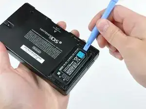
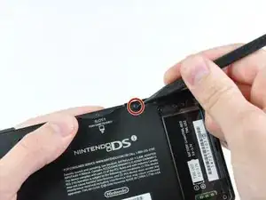
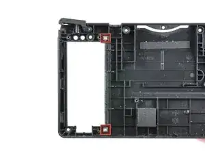
    • Two screws are hidden underneath two rubber feet highlighted in red.

    • Use the tip of a spudger to pry the rubber feet out of the lower case.

    • Depending on the age of your device, the rubber feet may crumble apart as you pry them out. If so, use a fine-tipped tool to scrape out any stuck pieces of rubber.

    One of the feet did break on me, tweezers came in handy for picking it out

    Willie Narvaez -

    I unfolded and sharpened a paperclip. You can use that to stab and hook the rubber without tearing it, as the rubber is thick enough to reseal when reinserted.

    Keegan Andersen -

    Nasty, broke my spudger and the feet in this step.

    TimedIn -

  4. MPpnnO22qoYDH1YH
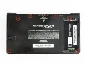
    • Remove the following screws securing the lower case to the body of the DSi:

    • Six 5.2 mm Phillips #00 screws.

    • One 2.7 mm Phillips #00 screw.

    Impossible d'enlever les vises… trop serré! comment faire?

    evrobert03 -

    i can't get the screw by the gamecard slot out, PH#00 is too small and PH#0 is too big

    Iblowup -

    same problem here. maybe try a JIS?

    darth mango -

  5. MqTKErbDcomH6eMJ
    MqTKErbDcomH6eMJ
    HuePUMK6TciCQZEj
    OkwvvvtBbd53ugBG
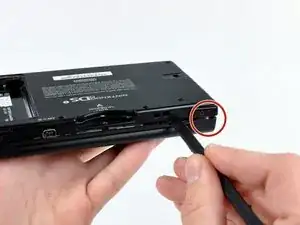
    • Insert the spudger in between the lower casing and lower panel near the top right corner of the DSi.

    • Carefully run the spudger along the edge of the outer casing, creating an opening between the body and the casing.

    • Continue running the spudger around the body of the DSi until the majority of the lower case has been separated.

  6. ZsX1F2YxXpOFEtuH
    ZsX1F2YxXpOFEtuH
    BS25HSFVrSclu2X1
    • Carefully lift the lower casing from its bottom edge.

    • The lower case is still attached to the motherboard by the volume and SD board cable highlighted in red. Do not try to completely remove the lower case of the DSi yet.

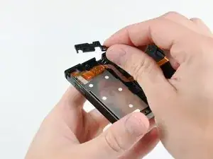
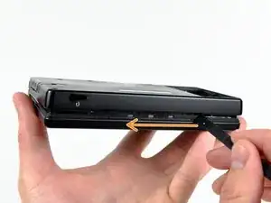
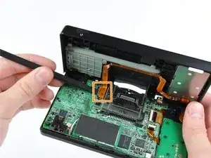
    • Pry the volume and SD board cable up from its socket on the motherboard using a spudger.

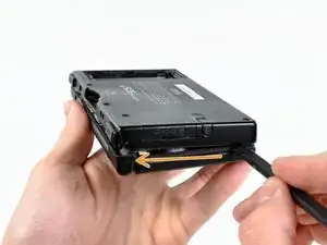
    • Once the cable is completely removed, then you may take off the entire outer casing.

  7. vlrfojiCfa3hnvCT
    • Pull the stylus straight out its housing and remove it from the rear case.

  8. brCR2KUpcOPZQluL
    • Remove the five 3.9 mm Phillips screws securing the stylus holder to the rear case.

  9. xHqWo1SdFAJmqqcE
    xHqWo1SdFAJmqqcE
    ej12hwcOJTsAmhMf
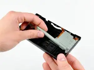
    • Lift and remove the left plastic protector from the DSi's rear case.

    • Grasp the stylus holder from the left side and lift upwards to remove it from the DSi.

  10. OSxgmIAwThd2vTHl
    • Lift the right trigger button cover out of the rear case.

  11. smmhVwIogBZOo1HV
    smmhVwIogBZOo1HV
    WaBTMj5RktjDdEZD
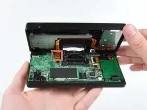
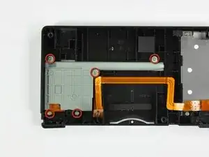
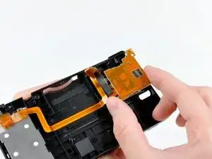
    • Lift and dislodge the SD board from its housing within the rear case.

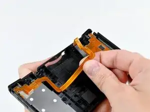
    • Peel the trigger buttons/SD board cable of its channel in the rear case.

  12. RfWJByPK3Z5BStVr
    RfWJByPK3Z5BStVr
    JyL3pAFCYl4pmqR1
    GyYoAOPOGqMVQSaB
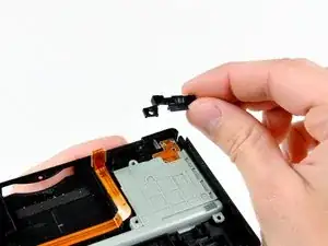
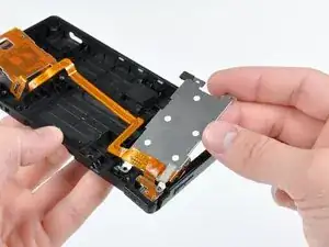
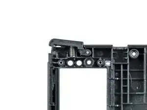
    • Lift the steel battery tray out of the lower case and remove the trigger button/SD board assembly.

    • When removing the trigger button/SD board assembly, don't lose the two steel nuts (highlighted in red) inserted into the lower case.

    • If your trigger button happens to fall apart during diassembly, the third picture shows its correct installed orientation. Be sure the spring is installed in the position shown, and that the two trigger button covers are unique to the side they are supposed to be installed in.

Conclusion

To reassemble your device, follow these instructions in reverse order.

Walter Galan

694047 Reputation

2 comments

I noticed some pencil marks on the inside of the lower shell that must have come from the factory. There is an m/ to the right of the foam pad, an ax to the right of that, and some kind of numeric marking that says 1T7 12 above the ribbon cable. I'm wondering if it has any significance.

Matthew Maulding -

Hi! I accidentally stripped the screws above the game slot , any ideas how to unscrew it without breaking my dsi?

Akbar Afandi -