Introduction

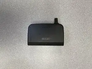
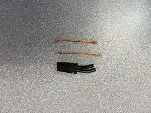
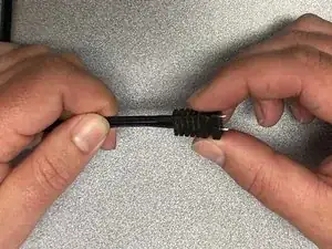
How to replace the power cable on an N64 power supply.

  1. CYirEqfF3VgM11dK
    CYirEqfF3VgM11dK
    sWcKFyP4TEWFUDpu
    • Unscrew the 2 security screws on the corners of the case using a 4.5mm security bit driver.

  2. FL2LDyuIAq1QsEL6
    FL2LDyuIAq1QsEL6
    ckUfaSslC6TUh1To
    • Remove the cover by gently prying from the side with the screws.

    • There are two clips that will let loose on the opposite side as you pry.

    • This will expose the circuit board needed for the repair.

  3. mgh62LPeuuk1OWXY
    • Remove the circuit board from the other half of the plastic case by pulling it straight out

    • There may be some adhesive holding it on to the plastic

  4. mtFT4rDVTo3LPO15
    mtFT4rDVTo3LPO15
    FSxYGlrLbgOOwVqD
    • Remove the original power leads by melting the solder using a soldering gun.

    • You will need to pull the wire from the backside but use caution to not touch any metallic parts as they will be hot.

    • If you do not know how to solder, read this Soldering Skills guide on ifixit.

  5. o1TmuIdWUFi5Xj5w
    o1TmuIdWUFi5Xj5w
    VKymTEurXTT45UkB
    xIKigLZUNuRAXc3Y
    • Clear the boot by pulling the copper wires out with pliers.

    • This will leave the wire sheathing which can then be cut flush with sharp knife.

    • Tip: Sand cut the end with fine grit sandpaper if desired.

  6. FeuEIfXPqpNHZvcZ
    FeuEIfXPqpNHZvcZ
    Df5lSsEGkySgMPlJ
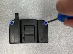
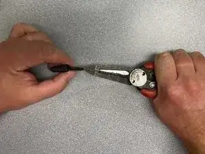
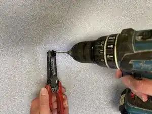
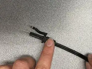
    • Use the drill to drill out the wire sheathing.

    • Drill each hole twice.

    • First, use a 5/64th drill bit. Then, use a larger 1/8th drill bit to finish.

    • The holes should be clean and free of debris once complete.

  7. iedXsLusFuRMRlZX
    iedXsLusFuRMRlZX
    ys3iakwYTxWFjbL4
    NBe1ebVsR5Aykxbv
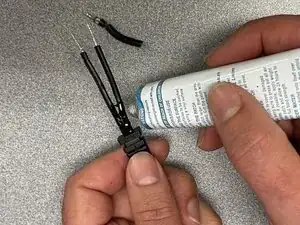
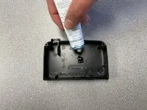
    • Feed the new cable through the boot .

    • Glue it in place by applying glue to the wire (close to the desired location of the boot) and sliding the boot into place.

    • Be sure the exposed wire length is close to the original.

  8. bWbEc2taeITf4OWk
    bWbEc2taeITf4OWk
    jkmAQQ1LfxTDIvOp
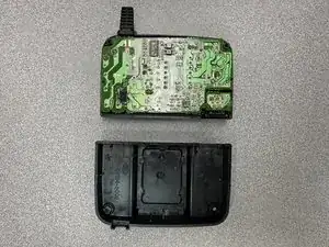
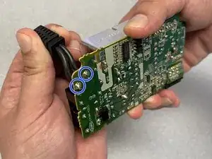
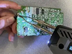
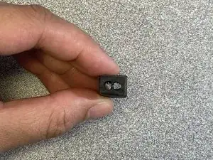
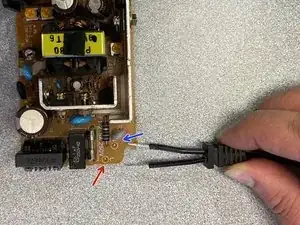
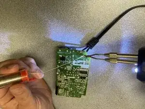
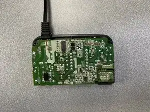
    • Align the wires with their original positions on the circuit board.

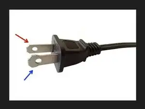
    • Looking at the component side of the board, the hot side is marked with an L for load and the neutral is marked with an N.

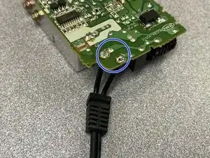
    • The neutral wire goes here, the hole closer to the center of the circuit board.

    • The hot wire goes here, closer to the outside.

    • The neutral wire can be identified by the wider prong on the plug end of the cord.

    Hola una preuguta me podrian proporcionar los datos del varistor V1

    Seme quemo y no seven los datos porfavor

    Adriam Paz Umaña -

  9. sq3WpIm24ah46etd
    sq3WpIm24ah46etd
    Nkj6wiSFibrIxCKO
    • Solder the new wires onto the circuit board.

  10. cldYqQOwYaHlIMGn
    cldYqQOwYaHlIMGn
    LfTxUqnCENIdYVUX
    • Use a flexible glue to put on the original adhesive.

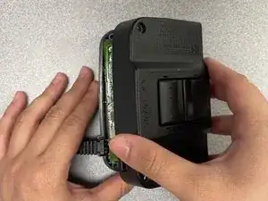
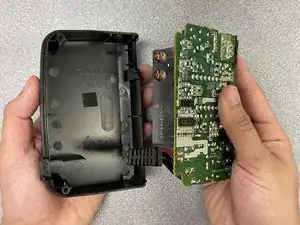
    • Insert the board, aligning the boot with the slot.

Conclusion

To reassemble your device, follow steps 1-3 in reverse order.

Brandon Clausen

Member since: 23/06/23

181 Reputation

0 comments