Introduction
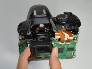
If there is dust in the viewfinder, or the screen gets cracked, it should be removed and/or replaced.
Tools
-
-
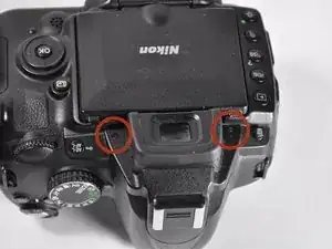
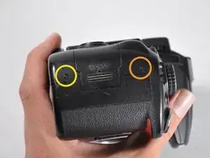
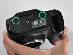
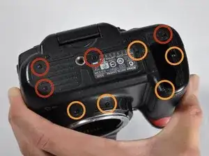
Unscrew the eight Phillips #00 screws on the back panel:
-
Two 2.5x6mm screws above the screen.
-
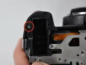
One 3x6mm screw on the upper part of each side (two total; right side shown).
-
One 3x7.5mm screw on the lower part of each side (two total).
-
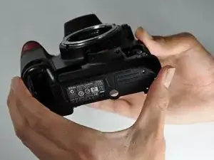
Two 3x4.5mm screws on the bottom.
-
-
-
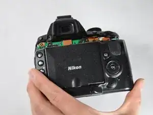
Pull the back panel up, then tilt it back. There will be two cables still holding it on.
-
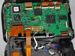
Disconnect the ribbon cable by flipping the black tab up, then pulling the cable out.
-
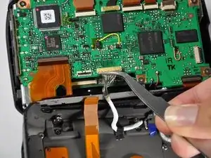
Pull out the other connector by lifting it up with tweezers, or by prying it out. Fingernails also work well.
-
-
-
Remove the bottom panel's nine Phillips #00 screws:
-
Four 3x3mm black screws.
-
Five 3x6mm black screws.
-
This 3x6mm screw is hidden under the wall adapter cover.
-
Pull the bottom cover off.
-
-
-
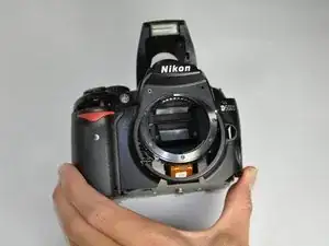
The front panel is next. Six screws hold it on.
-
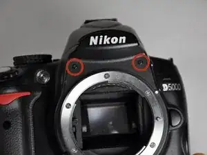
Start by removing four Phillips #00 screws in the top part of the panel:
-
Two black 2.5x4.5mm screws above the lens mount.
-
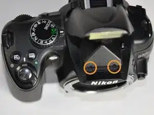
Two black 2.5x4.5mm screws under the flash (they are the same type of screw as in the above step).
-
-
-
Remove two more Phillips #00 screws from the bottom of the camera:
-
One silver 3x4.5mm silver screw, by the right edge.
-
One silver 3x4.5mm screw in the battery compartment.
-
Pull the front panel up and off.
-
-
-
Next is the top panel. It is held on by four Phillips #00 screws:
-
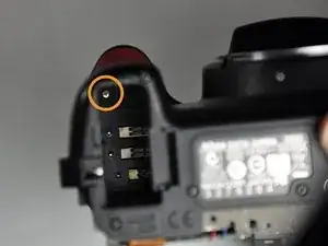
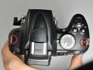
Two 3x3.5mm black screws, one by each of the strap mounts.
-
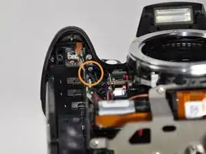
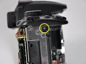
One silver 3x5mm screw on the underside of the panel, about where the "Info" button is. It is the lower of the two in this area, and farther back in the camera.
-
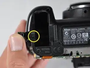
One 3x3mm black screw in the side, under the plus/minus button.
-
-
-
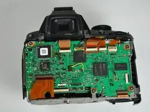
Disconnect the third ribbon cable from the right at the top of the back logic board.
-
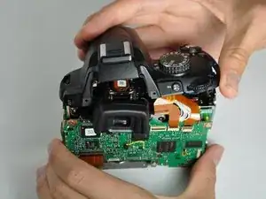
Lift the top panel up.
-
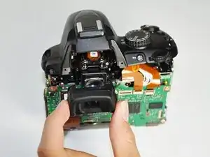
Remove the viewfinder hood by pulling outward.
-
-
-
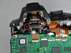
Remove the two Phillips #00 3x5.5mm silver screws securing the viewfinder assembly.
-
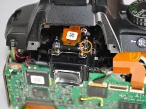
Remove the three Phillips #00 2.5x3.5mm screws holding the electronics board onto the viewfinder assembly.
-
These are the lower screws in the metal plate, not the upper ones with the springs on them.
-
-
-
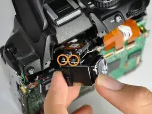
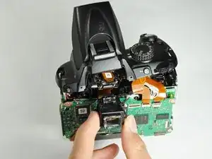
Remove the viewfinder window.
-
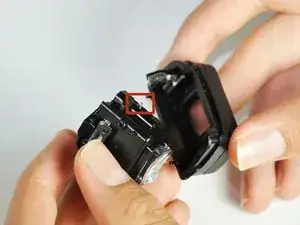
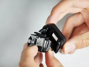
During reinstallation, there is a small tab on the side of the window assembly that needs to be reconnected (window removed for clarity).
-
To reassemble your device, follow these instructions in reverse order.
One comment
So, would it then also be possible to not only clean or replace the viewfinder, but swap out a pentamirror with a pentaprism or upgrade a viewfinder from this?
