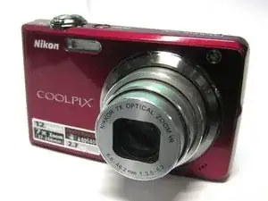
Introduction
Visit our troubleshooting page for help with diagnosing your Nikon Coolpix S630. If the lens needs to be replaced, this guide will help you accomplish that. Gather all of the tools that are listed below before you begin.
-
-
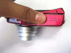
The battery compartment is located on the bottom of the camera.
-
Place your thumb on the battery door.
-
Slide the door away from the camera in the direction the arrow points to.
-
-
-
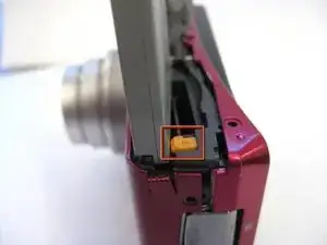
Slide the yellow tab towards the back of the camera.
-
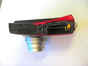
The battery should pop out.
-
Remove the battery.
-
-
-
Press the memory card down into the camera.
-
The memory card should pop out.
-
Remove the memory card.
-
-
-
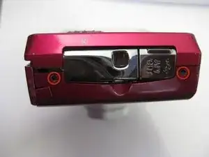
Unscrew the two 3.5mm Phillips screws from the side with the AV outlet.
-
Unscrew the 3.5mm Phillips screw from the opposite side of the camera.
-
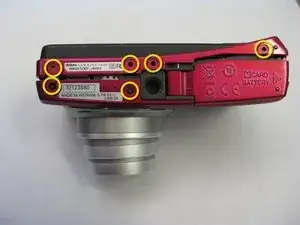
Unscrew the six 3.5mm Phillips screws from the bottom of the camera.
-
-
-
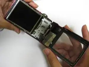
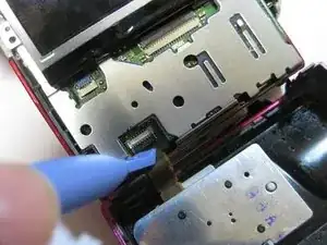
Place the plastic opening tool underneath the ribbon tab as shown. Gently lift the tab up.
-
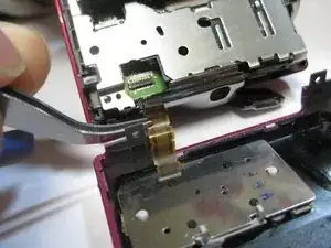
Gently pull the ribbon from the logic board with tweezers.
-
With the ribbon disconnected, the back casing should now be detached from the rest of the camera.
-
-
-
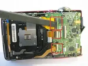
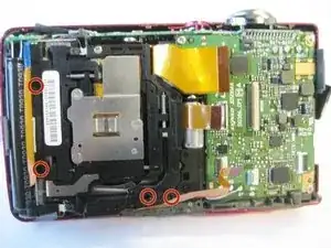
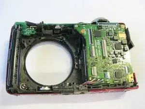
Remove the metal casing from the logic board.
-
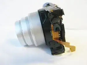
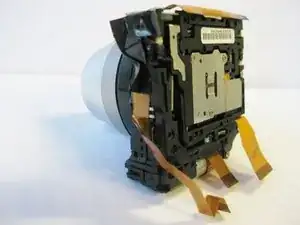
There are three ribbons that connect the lens to the logic board as shown.
-
Place the flat end of the spudger underneath one of the black flaps. Carefully lift the flap with the spudger and gently slide the ribbon out.
-
Repeat the above process to remove the remaining two ribbons.
-
To reassemble your device, follow these instructions in reverse order.
One comment
Between steps 6 and 7 there should be a step to remove the LCD screen, metal casing and ribbon cables.
There is a 5th screw required to remove the lens in step 8. It’s under the fat ribbon cable. Deep in a hole.
Rob G -