Introduction

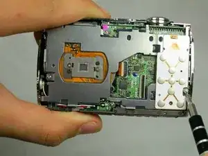
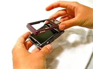
This guide will show how to access the motherboard which will give you the ability to remove the lens and flash.

  1. TtOJYPG2fP3hxaTD
    • Remove the two 2.8 mm screws on the left side of the camera.

  2. DfD4kSCQJAqCP3cA
    • Remove the four 2.8 mm screws on the right side of the camera.

  3. ddUtZJHUb1nWWKFc
    • Remove the three 4.1 mm screws on the bottom of the camera.

  4. YDPFYhpjqMh55AaR
    • Gently lift the rear cover from the camera.

  5. VpmbtLIVJJHeiJOK
    • Gently lift the screen out of its place.

    • You will need to hold the screen slightly above the camera because it will still be attached to the camera by an orange ribbon cable.

  6. 2mvWZsq33mthc3Rf
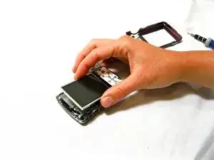
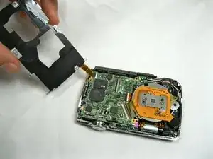
    • Use the tweezers to lift the ZIF connector which is holding the ribbon cables that connect the LCD screen to the motherboard.

  7. bXFkarVdNrLGZCTw
    • Slowly pull the screen from the camera.

  8. SRYMpcvcQLVkvnUq
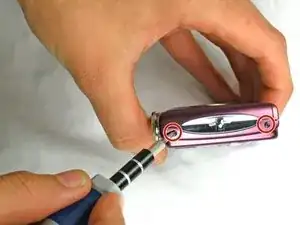
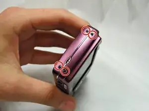
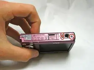
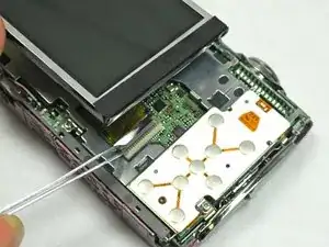
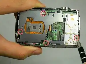
    • Remove the four 3.8 mm screws located near the bottom right and top left of the LCD base plate.

  9. mSwCqFZs6JsPpRF1
    • Lift up silver LCD base plate

  10. YYEqRUIBUitERWIA
    YYEqRUIBUitERWIA
    oRDMiEmWQysGOTBZ
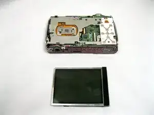
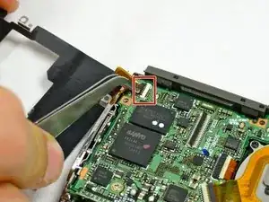
    • Using tweezers, lift up the retaining flap on the ZIF connector securing the button panel ribbon cable.

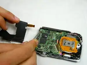
    • Slide the button panel ribbon cable out of its socket on the motherboard.

Conclusion

To reassemble your device, follow these instructions in reverse order.

Shauna

Member since: 05/04/11

798 Reputation

One comment

It would be nice to have a guide for replacing the flash capacitor.

danwat1234 -