Introduction

The CCD sensor can be sensitive to scratches and other contaminants that would disrupt its surface yielding blurry images. This guide will provide the procedure necessary to replace this component.

  1. Yt6PZvfWZtOdhIBJ
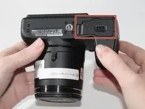
    • Identify the battery chamber found at the bottom of the device.

    • Ensure the camera is turned off before conducting any maintenance on the device.

  2. sYxyP1yT6K5cufyR
    sYxyP1yT6K5cufyR
    QVxQLYWv51QFOlJj
    xfni1Hy5YaxndvW6
    • Slide the switch to the left to open the battery chamber using your fingertip or plastic opening tools.

    • The spring loaded battery chamber door will swing open after the switch is moved.

  3. KYBSDoYA46YoufP5
    KYBSDoYA46YoufP5
    SSnZVxJNYsgRxSfA
    nO5UPLDQT4eSjIEB
    • Depress the yellow spring loaded tab holding the battery in place using your fingertip or plastic opening tools.

    • After the yellow tab is depressed, the battery should partially eject from the camera.

  4. VtXWNA1vJhRUSLaV
    VtXWNA1vJhRUSLaV
    pGLA4YnPy4qkQ5EN
    • Gently remove the battery from the chamber.

  5. oLRBGhIQS3lV6cph
    oLRBGhIQS3lV6cph
    TZLlEGWovlPQy3EK
    aNtIIBWNO4kt33ho
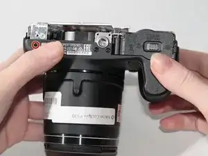
    • Remove the six 4mm screws highlighted in red with the Phillips #000 screwdriver.

    • Remove the 5mm screw highlighted in orange with the Phillips #000 screwdriver.

  6. CnFSypUYDFGkLgrH
    CnFSypUYDFGkLgrH
    amARfiWFM5Mc4lmu
    opEEGJQq31iHQFsF
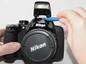
    • Pop up the camera flash using the button below the lightning bolt on the left side of the camera.

    • Identify the small notch below the camera flash where the body of the camera and the back cover join.

    • Use plastic opening tools to pry the darker plastic piece under the camera flash from the lighter plastic camera body.

  7. wLrBtcYMUjlrb4sn
    wLrBtcYMUjlrb4sn
    eA1kuVeRYHFE1XhV
    CAc6JYHHtMIKqxWa
    • Gently pry with a plastic opening tool around the perimeter of the camera.

    • The plastic HDMI cover can become loose and fall off during this step. Once the back cover is free from the camera you may remove this piece to store in a safe place.

  8. lIGXDParRIujF2WD
    lIGXDParRIujF2WD
    wpHLasOMtvcwJ2sl
    fPhJbdXdqRAMU6RV
    • Gently lift the back cover away from the camera body.

    • A gold ribbon cable will join the back cover of the camera to the internal electronic components. Be careful not to remove the back cover without removing the cable since this part can easily break.

    • To remove the ribbon cable, gently pull the connector from the camera's internal electronic components using a pair of tweezers.

    • Flip the orange bar securing the ribbon cable upwards to allow for safe removal.

  9. ZnkFhkvu3U345oex
    • After the ribbon cable is removed from the camera body, the cover can be completely removed.

  10. OLaLFAbuYXnaTw6I
    OLaLFAbuYXnaTw6I
    6NKwNjsiueNlbAUD
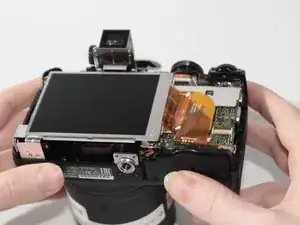
    • Lift the LCD screen upwards.

  11. lEAeZTFEfFREELM6
    lEAeZTFEfFREELM6
    WcITxVIyiMvLtGju
    • Tilt the screen towards the ribbon cable.

    • Remove the ribbon cable by gently pulling the cable away from the motherboard using tweezers.

    • Flip the orange bar securing the ribbon cable upwards to allow for safe removal.

  12. 4kDRxi21gShhIwKF
    4kDRxi21gShhIwKF
    k1islPYeeMxFwEPp
    • Remove the six 4mm screws highlighted in red using the Philips #000 screwdriver.

    • Remove the 6mm screw highlighted in orange using the Philips #000 screwdriver.

    • One of the 4mm screws is on the exterior of the device.

  13. HivUDU1qqGRSy3Xu
    HivUDU1qqGRSy3Xu
    E3gvCF24uvDd4OLb
    mMXiJspl3E6OUlCM
    • Lift and remove the LCD mounting bracket to expose underlying hardware.

  14. CYqZ3JJdPLW4oFJD
    CYqZ3JJdPLW4oFJD
    miWGgRJLrmAcOrG2
    3FoVUelfZUrGDYO5
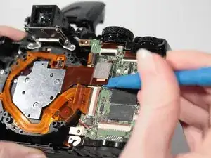
    • Disconnect the ribbon cable connector by prying upwards on the part using the plastic opening tools.

  15. LXuOJxYlFN6NB2bB
    LXuOJxYlFN6NB2bB
    xedGjdq1F2X1BmLN
    4GSOVT2VF2BDMImx
    • Remove the 3mm screws highlighted in red using the Philips #000 screwdriver.

    • There should be a total of three screws removed in this step.

  16. lBFGtkJwNDCLpHXB
    lBFGtkJwNDCLpHXB
    vIqULU2KgNtgRtYu
    i62G4yEKlaSiLHvL
    • Use the tweezers to remove the CCD sensor carefully.

Conclusion

To reassemble your device, follow these instructions in reverse order.
Alan Weihe

Member since: 01/02/16

998 Reputation

0 comments