Introduction
If the screen does not power on, even when the camera itself is powered on, the LCD screen could be broken. This guide will show the proper instructions for replacing the screen.
Tools
-
-
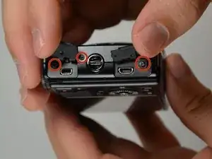
Remove the three 4 mm screws from the bottom of the camera using a #00 Phillips screwdriver.
-
Remove the single 3.5 mm screw from the bottom of the camera using a #00 Phillips screwdriver.
-
-
-
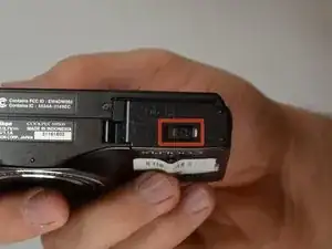
With the bottom of the camera facing you, slide the latch on the compartment to the left.
-
Swing the battery compartment door open.
-
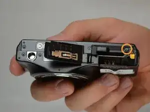
Remove the 3.5 mm screw from the inside with a #00 Phillips screwdriver.
-
-
-
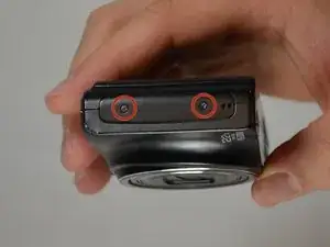
With the screen facing you, locate the two 3.5 mm screws on the left face of the camera. Remove them using a #00 Phillips screwdriver.
-
-
-
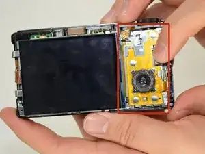
With the screen facing you, locate the three 3.5 mm screws on the right face of the camera. Remove them with a #00 Phillips screwdriver.
-
-
-
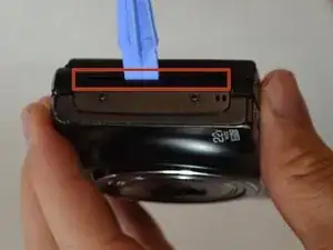
Locate the crease where the case comes together.
-
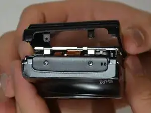
Using a plastic prying tool, pry at the line to remove the camera case.
-
-
-
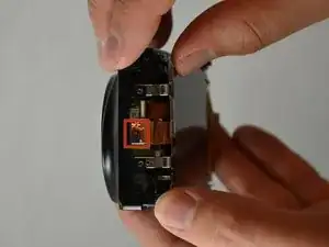
Locate the magnet and copper tape on the left side of the camera.
-
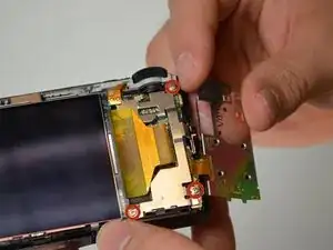
Gently pull the copper tape off of the metal plate.
-
-
-
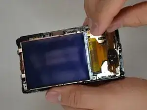
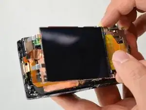
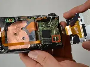
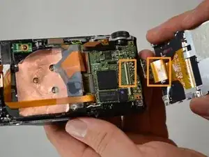
Lift the screen up and swing it to the right, exposing the circuit board underneath.
-
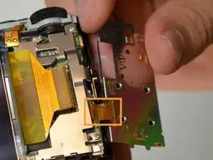
Detach the ribbon cable that is connecting the LCD screen and the circuit board.
-
To reassemble your device, follow these instructions in reverse order.
One comment
In step 9, you should mention the small circuit board that has to be released from the screen on the top right of the screen. (It can been seen in the step 6 picture.) It would also been helpful if you mentioned the flange on the ribbon cable connector that should be loosened to allow the cable to be disconnected. The guide allowed me to disassemble and reassemble the unit with a new screen, but the camera was totally inoperative afterwards (would not turn on or charge at all) so I can’t say the guide was helpful.
