Introduction
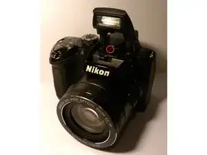
This guide will demonstrate how to remove the mother board from your camera.
Tools
-
-
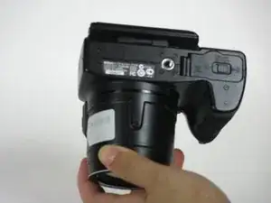
Press down and forward on the battery cover latch.
-
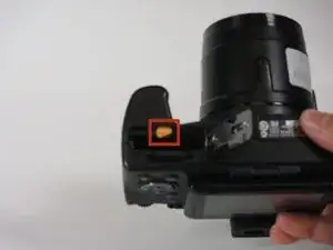
Push the orange latch, in the direction of the arrow on it, to release the battery.
-
-
-
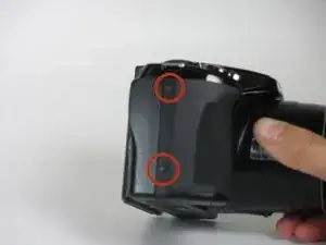
Remove all the marked screws using a PH00 screwdriver.
-
Remove the two 3mm screws on the grip.
-
Remove the two 4mm screws on the side opposite the grip.
-
Remove the three 4mm screws on the base of the camera.
-
Remove the four 3mm screws on the base of the camera.
-
-
-
Remove the 2mm screw from the microphone metal grid using a PH00 screwdriver.
-
Remove the 4mm screw that was under the metal microphone grid using a PH00 screwdriver.
-
-
-
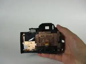
Separate the two parts of the body of the camera slightly.
-
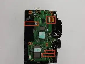
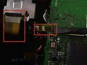
Release the two cables by lifting up their respective clips with a spudger.
-
-
-
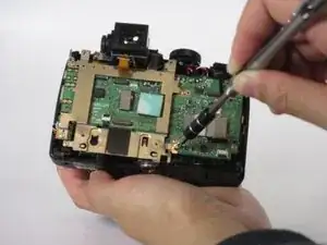
Use a PH00 screwdriver to unscrew the four labeled 3mm metal screws on the metal backing.
-
Remove the four labeled 4mm screws connected to the motherboard.
-
Remove the metal support.
-
-
-
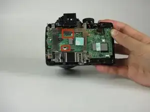
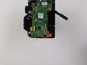
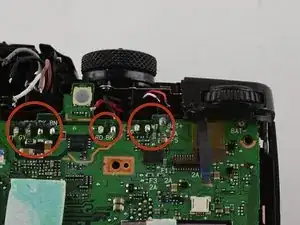
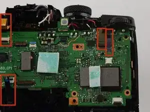
Use a spudger to unlock the labeled connector ribbons.
-
Disconnect the labeled connector ribbons.
-
To reassemble your device, follow these instructions in reverse order.
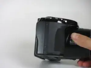










Before separate the two parts of the body of the camera as described in step 3, we have to remove the two screws hide behind the screen (at the base of the gear)
donthavetoknnow -
Before to separate the two parts of the body of the camera as described in step 3, we have to remove the two screws behind the screen, in the base of the system that connect it to the camera
donthavetoknnow -
Yes Indeed a step was forgotten. You need to flip open the flash module. Now you can remove a small screw from the front that holds the stereo L R microphone in place, after that carefully remove the microphone cover. After that you will see a screw from the top view where the cover of the microphone was removed. When this screw is removed the back cover comes off. Please be careful because there are two ribbon cables, one for the buttons and one for the LCD screen.
PS I still have problems after replacing the complete lens assembly with sensor. I think Nikon updated the firmware and something in the firmware is faulty. Because I can still record movies but cannot make pictures (shutter button works)… Yes I tried hard reset, factory reset. No luck at all. The backup battery in my device is flat also…. Maybe I should buy another camera. No more Nikon for sure. Camera wasn't even used that much, meh ..
Roger L. Ortiz -