Introduction

  1. lGOwJFgfLs4GDZNH
    • Remove the screw located near the speaker port using a Phillips 00 screwdriver.

  2. ZD3ja13ACMXH2L2d
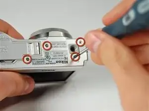
    • Turn camera upside down so that the battery compartment is facing you.

    • Remove all four screws from the bottom of the camera with a Phillips 00 screwdriver.

  3. V4tuHIcW5dnG6Wkf
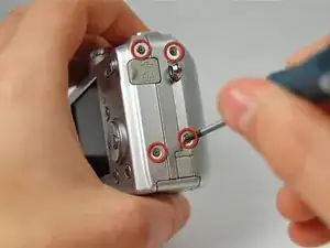
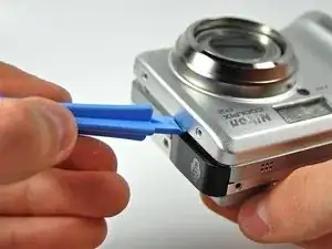
    • Rotate the camera to the opposite side where the A/V outlet is located.

    • Unscrew and remove all four screws with a Phillips 00 screwdriver.

  4. 3TKhcM12BSfCDxHh
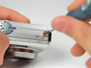
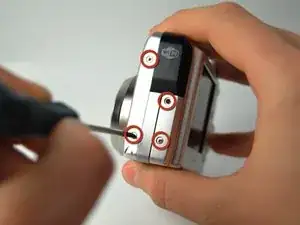
    • Turn the camera so that the Wi-Fi adapter is facing you.

    • Unscrew and remove all four screws with a Phillips 00 screwdriver.

  5. UcYJWq6wbpITK62O
    UcYJWq6wbpITK62O
    rGRCBSRrPDINKonM
    cvpLWOFPvEVpLUn5
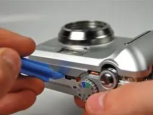
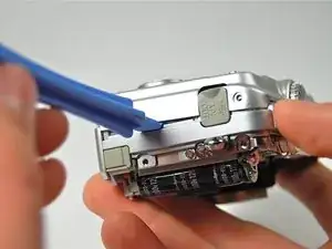
    • Using a plastic opening tool, pry the front casing of the camera.

    • Continue this motion all around the front casing of the camera.

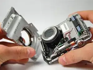
    • Gently pull apart the front casing from the rest of the camera.

  6. OxqaoEDNDY1jSda1
    • Using the plastic opening tool pry the back casing of the camera.

  7. BbNiYTfwK4QaSBlX
    • Orange ribbon is fragile

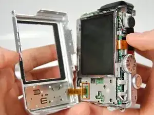
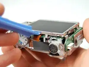
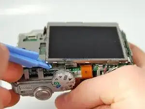
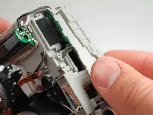
    • Carefully pull apart the back casing of the camera from the front of the camera without tearing the orange ribbon.

  8. tDsgQiEEjFeFsk26
    tDsgQiEEjFeFsk26
    RyKxiobBOgr4WSg6
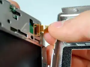
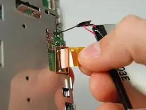
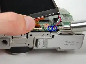
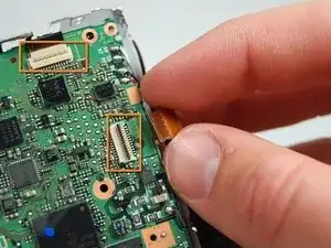
    • Pull down the on the black latch to carefully separate the orange ribbon from the motherboard.

    • Pull apart the orange ribbon and front casing from the rest of the camera.

  9. GkCiPBE6OH41Fb2G
    GkCiPBE6OH41Fb2G
    3ukc6SjXcERuO2UH
    • Use plastic opening tool to carefully pry the LCD Screen from the camera.

  10. KXHDWyNvFiAKJgJO
    KXHDWyNvFiAKJgJO
    foOeR3SBS32qHBvi
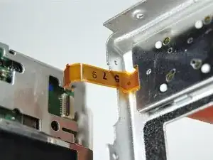
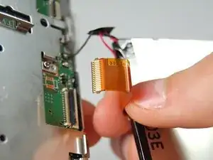
    • Gently pull the ribbon cable down to release the latch, then pull up to remove it from the motherboard.

  11. n6SyJK6Rvs4gMDqO
  12. KH4WGwgFNEU3HCOP
    • Continue by removing two screws from the back of the camera body.

  13. BtwAPIXApu3h6IKR
    • Remove the screw connecting the wifi card cover to the front of the camera.

  14. VXSHArcERkUDBKh6
    • Remove the final screw connecting the Wifi card cover to the case.

  15. MQhSd1gQLQcjbGPA
    • Gently pull the Wifi card cover off of the camera body.

  16. kkPIWEGStRJL2nmJ
    • Remove the screw holding the Wifi Card to the camera body.

  17. 3NPOOvVekNQALp4J
    • Gently pull the WiFi card out of the camera.

  18. COq4XsN3UPrvg6ZD
    COq4XsN3UPrvg6ZD
    2ampfjNTDdxXN5ha
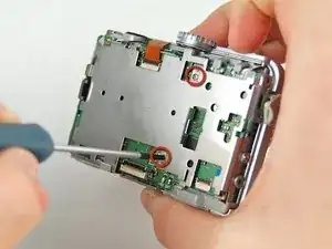
    • Continue removing screws from the outside of the camera body.

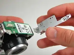
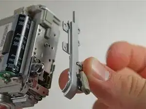
    • Next pull the plastic side panel off of the camera body.

    • Be extremely careful when holding the camera around the flash capacitor (circled in green), it is probably still charged, and it is very painful if you are shocked by it.

  19. TlYAEyKkUKreFiMx
    TlYAEyKkUKreFiMx
    dapdLWOP6drIcjWN
    Ar6nrPGpwnwKjo4g
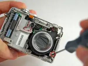
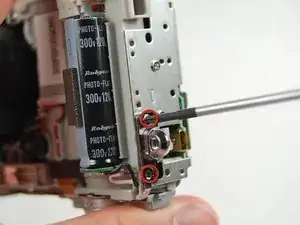
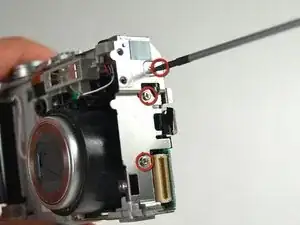
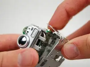
    • Remove the two screws connecting the strap loop to the camera body.

    • Remove the three screws from the left side of the camera body.

    • Remove the screw by the shutter button.

  20. DkxdQGclHeriojTm
    DkxdQGclHeriojTm
    bvRAPEVTUr1hYQPG
    • Remove screws from plastic side cover.

    • Pull off plastic cover.

  21. JfOIg511tyDUqxLy
    JfOIg511tyDUqxLy
    VhSP26MuMIQ14dtQ
    • Carefully remove the back housing body from the camera.

  22. tAYlnt1vrBgD5JAK
    tAYlnt1vrBgD5JAK
    l2rA32avSSEoePWu
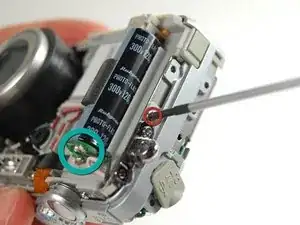
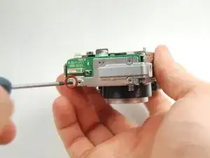
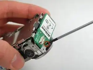
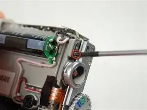
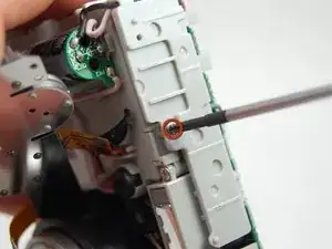
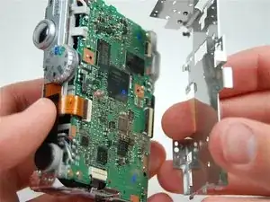
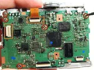
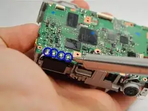
    • Remove the five screws connecting motherboard to the camera body.

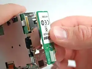
    • Carefully detach the two ribbon cables from the motherboard by releasing the black plastic catch, then pull the cables gently upwards out of the connector.

  23. 4xvuDd2MNEQv2syf
    • Carefully de-solder the four connections to the motherboard.

Conclusion

To reassemble your device, follow these instructions in reverse order.

Joshua Avery

Member since: 23/01/12

31 Reputation

0 comments