Introduction
Replacing the screen and connector ribbon.
-
-
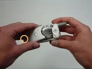
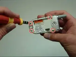
Use your T6 Torx Screwdriver to unscrew the four screws located on the back of the phone.
-
Remove the SIM card located on the back of the phone.
-
-
-
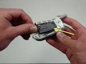
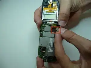
Unclip the pronged rectangle connector ribbon attached to the motherboard.
-
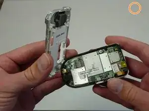
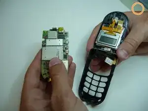
Remove the motherboard by lifting it up out of the keypad.
-
-
-
Power off the Motorola V180.
-
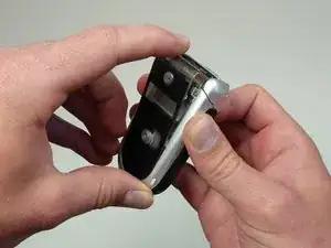
Flip the phone over to its back side.
-
Hold down the button and slide off the back cover.
-
Remove the battery.
-
-
-
Use your T6 Torx Screwdriver to unscrew the four screws located on the back of the phone.
-
Remove the SIM card located on the back of the phone.
-
-
-
Unclip the pronged rectangle connector ribbon attached to the motherboard.
-
Remove the motherboard.
-
-
-
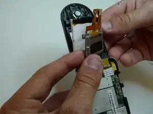
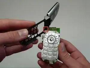
Now that the ribbon is loose, the screen (white part) can swing away.
-
Some of the black "tape" can be peeled back, but the screen is still attached. More work may be required to fully separate this part.
-
-
-
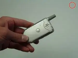
Slide out the part of the connector ribbon that was just attached to the motherboard through this narrow slot in the phone.
-
The entire connector ribbon unit can now be removed from the phone.
-


To reassemble your device, follow these instructions in reverse order.