Introduction
This guide should be used to open the modem to access inner components for repair or replacement.
Tools
-
-
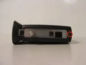
Locate the single 1 cm screw on the back of the device (enclosed by a red circle in the image).
-
Using a screwdriver with a Torx 10 hex screw, begin removing the 1cm screw by turning the screwdriver counterclockwise.
-
Remove the screw and set aside.
-
-
-
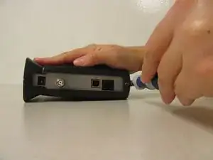
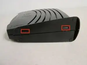
Locate the two horizontal slots on the bottom of the device.
-
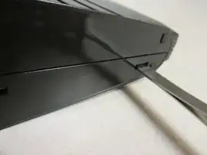
Insert the back end of the forceps into one of these slots. You may also use any other flat, narrow tool that fits into the slots.
-
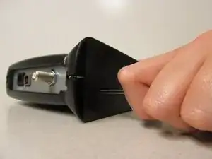
Gently push the forceps into device. You should feel movement or hear a click, signifying this side of the device is unlocked.
-
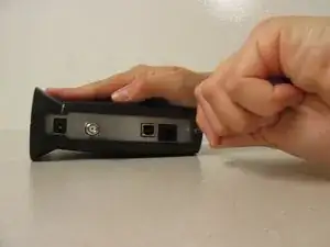
Repeat with the other slot to completely unlock the device.
-
-
-
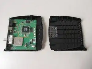
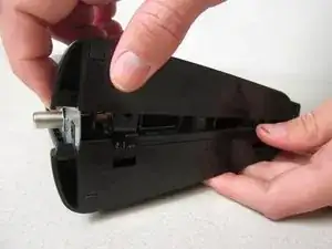
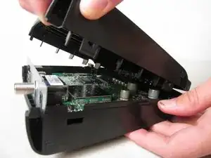
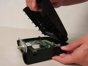
Grab the top and the bottom of the device and gently pull the device open.
-
Continue pulling until you have completely removed the top cover of the device.
-
In order to learn how to re-assembly your device, visit the Reassembly Guide.