Introduction

Prerequisite-only! This guide is part of another procedure and is not meant to be used alone.

Follow this guide to separate the motor from the crankcase on a Wacker BS50-4AS REV 101 (2019) Vibrator/Rammer to perform internal repairs.

  1. MLifHqlYxerSwXNl
    MLifHqlYxerSwXNl
    ipgNkCbKH1uGuLIO
    • Ensure the device is powered down and cool to the touch before starting your repair.

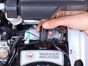
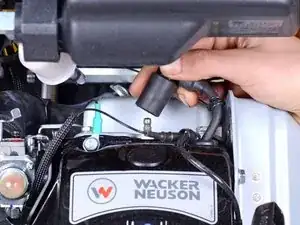
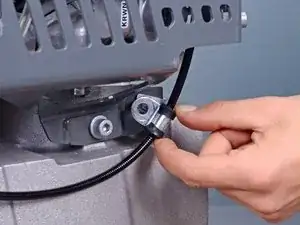
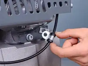
    • Firmly grip the base of the spark plug wire's connector and pull it away from the spark plug to disconnect it.

  2. gOcTOgwCYcgNLARX
    • Use a 1-1/16 inch socket to break loose the oil sight gauge near the bottom of the device.

    • Do not fully remove the oil sight gauge yet with the device in this upright position.

    • The oil sight gauge doubles as the oil drain and fill plug.

  3. WOcJDYG3ZNU1UeuV
    • Lay the device down horizontally with the oil sight gauge facing down.

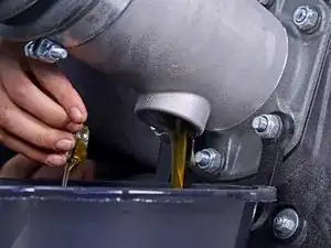
    • Position a shallow oil drain pan underneath the sight gauge.

  4. GkUmvjnGRiKiHSPy
    • Remove the oil sight gauge.

    • Let the oil drain until drips are infrequent.

    • Replace and retighten the oil sight gauge.

    • This model requires 0.7 liters of SAE 10W-40 oil.

  5. sBLtBfNhU3JIHtMX
    sBLtBfNhU3JIHtMX
    OPCUyUVWTgcKJWDb
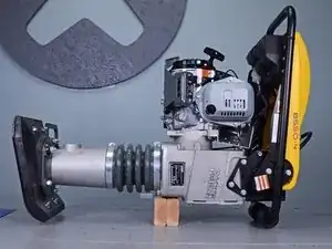
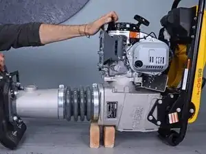
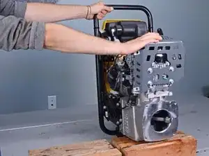
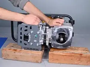
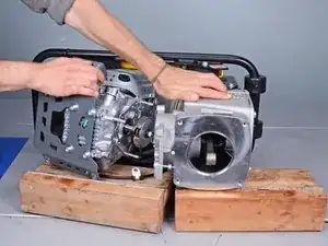
    • Flip the device onto the work surface such that the motor and handles face up.

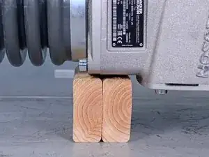
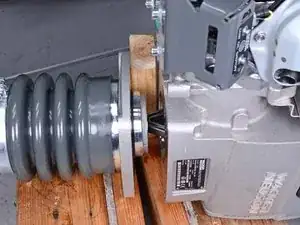
    • Place two separate blocks of wood underneath the seam between the leg assembly and crankcase.

    • Once the two halves separate, each side will need to be supported.

  6. QahNJt34QUdEFEoq
    QahNJt34QUdEFEoq
    SZOVqjcjQUDdOON2
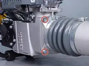
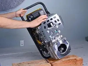
    • Use an 8 mm hex key socket to remove the four bolts securing the leg's guiding cylinder to the crankcase.

    • You may need to use an impact driver or breaker bar to break these bolts loose.

    • During reassembly, ensure each bolt has its accompanying lock washer.

  7. cWYx4EptleW3FJ2A
    cWYx4EptleW3FJ2A
    WDsrkEpDKryQugpN
    • Pull the leg assembly away from the rest of the device.

    • Ensure each half stays adequately supported.

  8. lFU6ojegjZGXJVyN
    lFU6ojegjZGXJVyN
    ceYMi6vdiMvQO4i3
    yLXPW4UqcG6IgU1N
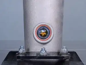
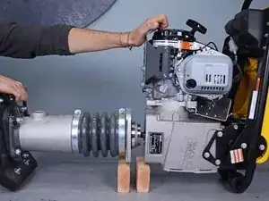
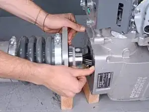
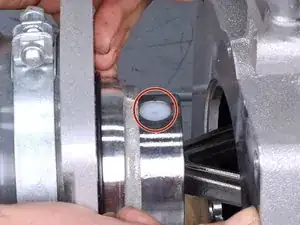
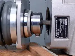
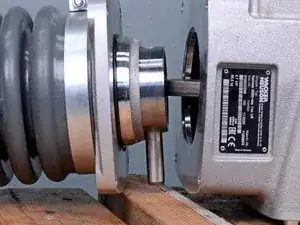
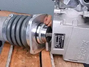
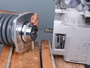
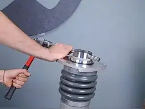
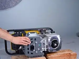
    • Continue to separate the two halves by compressing the bellows until the nylon plug covering the piston pin is visible.

  9. kl6vqGBXSPv1gyAx
    kl6vqGBXSPv1gyAx
    KJ2VsAU1kyGBSZyd
    • Tip: To compress the bellows, insert a block of wood between the two halves and pivot the leg assembly off of the crankcase to compress the guide cylinder, revealing the pin.

  10. 1WEO5sFB6nKCByEt
    1WEO5sFB6nKCByEt
    oeX1ZFKp6LH1E2FS
    mMxRMSpLW5wDxsIo
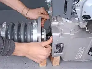
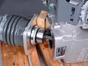
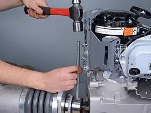
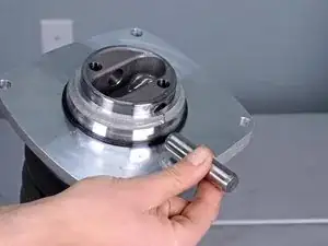
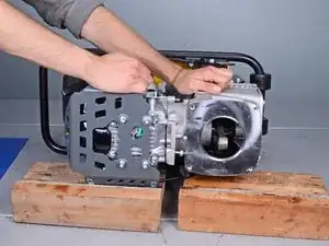
    • Use an appropriately-sized punch and a ball-peen hammer to tap the pin out of its hole on the guide piston until it is no longer securing the connecting rod.

    • Once the piston and connecting rod are separated, the two halves become completely disconnected and will need to be adequately supported.

    • During reassembly, ensure that both nylon plugs are reinstalled and are flush with the surface of the guide piston.

  11. 6lQwbolJ5KTIwFht
    6lQwbolJ5KTIwFht
    oByAJJ6SWgFNfOTb
    • Remove the leg assembly from the crankcase.

  12. 5G6sqYQQwxpjyQw4
    5G6sqYQQwxpjyQw4
    IrHvirlxHaFfdmE6
    • Use a punch and hammer to tap the pin out of the guide piston.

    • Once the pin is removed, the guide cylinder may spring up due to the compression of the bellows.

    • During reassembly, the bellows will need to be compressed to uncover the pin hole on the guide piston.

  13. RtVeUyQAOC6Pj1Sc
    • Use wood blocks to support the device on the work surface, motor facing up.

  14. vSWUwU1IpTCrXHTF
    • Use a 6 mm hex socket to remove the engine guard bolt securing the cable guide.

  15. YuXiwfKNVKPEpgGs
    YuXiwfKNVKPEpgGs
    HmLQksWRadvgEEFV
    • Pull the cable guide away from the engine guard.

  16. XeDdFnC3Emt16iLj
    XeDdFnC3Emt16iLj
    KAgbJFZInySQsaFe
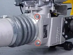
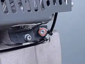
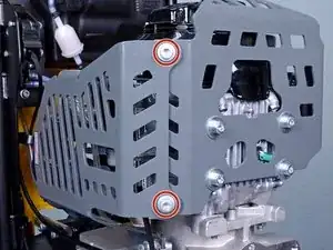
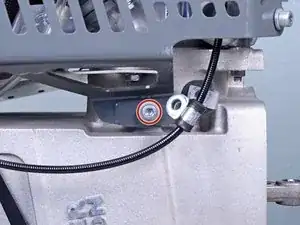
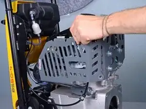
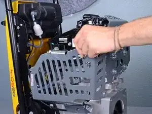
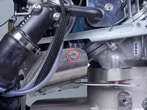
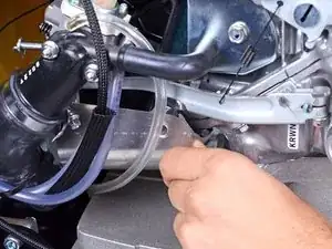
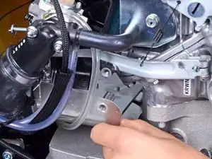
    • Use a 6 mm hex socket to remove the three remaining bolts securing the engine guard: two on the outer edge and one near the crankcase.

  17. iTByMU6Uic2fKYkm
    iTByMU6Uic2fKYkm
    XnT4IcndfK16oC6M
    • Remove the engine guard.

  18. B2hYPMB6Jr4LEQaN
    B2hYPMB6Jr4LEQaN
    4UxgdJk56YVceFMv
    LXwxfK4k2ryox4KD
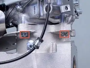
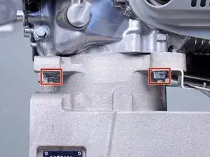
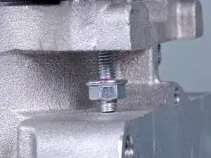
    • Use a 13 mm wrench to remove the four nuts securing the motor to the crankcase, two on each side.

    • When removing the nuts, the crankcase bolts may also become unthreaded, preventing its accompanying nut from being removed. This is fine.

  19. RT3ES41S2VdGfY2w
    • Use a 10 mm socket to remove the bolt securing the muffler shroud.

  20. ammsSJftvZ2XEVxV
    ammsSJftvZ2XEVxV
    3kSh4PXieEVBSQ2N
    • Lower the muffler shroud away from the motor, down onto the crankcase.

    • Do not fully remove the muffler shroud.

  21. SAqWGFZB1R4ZWFdN
    SAqWGFZB1R4ZWFdN
    re2HvcQVIVTEqVvl
    ZM5kDeR1LXxbCUsU
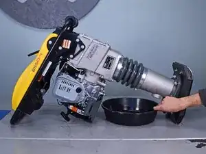
    • Tilt the device down onto its side, supporting both the crankcase and motor with blocks of wood.

    • The motor is loose from the crankcase, so support the motor as you lower the device down.

  22. qGHNJwCHCxBIk4EW
    qGHNJwCHCxBIk4EW
    LNbLs6Yfwdi5fRAj
    sweLvqundixq2yEq
    • Hold the crankcase steady and pull the motor directly away from it.

    • Ensure each half stays adequately supported.

    • The motor is still attached to the rest of the device via various hoses and cables, so don't attempt to completely remove it.

Conclusion

To reassemble your device, follow these instructions in reverse order.

Carsten Frauenheim

Member since: 10/03/20

110978 Reputation

0 comments