Introduction

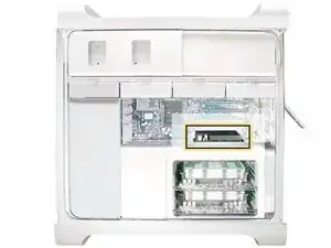
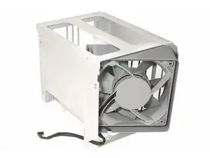
Removing and/or replacing the Memory Cage with Rear Fan.

  1. baGFXrEPgYaBBPBn
    baGFXrEPgYaBBPBn
    vE6oorNktmNIVlMw
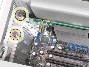
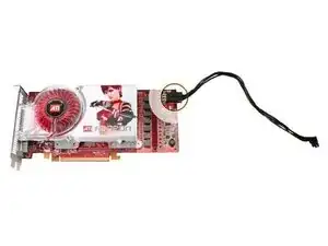
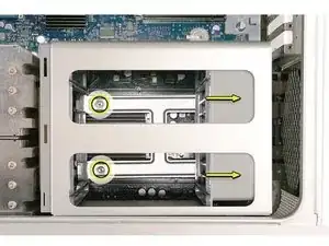
    • This procedure explains how to remove a standard card and a card that includes a booster cable. Before you can remove either type of card, however, you must first loosen the two captive screws that secure the PCI bracket to the enclosure and remove the bracket.

  2. IPVTKPcsIBNVf1HA
    • Handle the card only by the edges.Do not touch its connectors or any of the components.Lift the card straight out from the connector to remove it, and insert it straight into the connector to install it.Do not rock the card from side to side and don’t force the card into the slot.Once the replacement card is installed, pull on it gently to check.

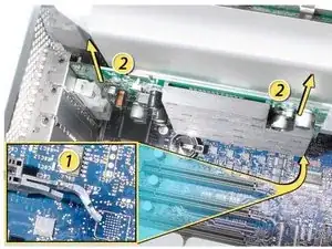
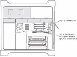
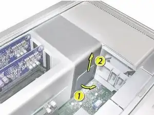
    • 1) Release the small locking clip at the front of the card’s logic board connector by pushing the clip up toward the media shelf.

    • 2) Holding the card by the top corners, pull up the card and remove it from its expansion slot.

  3. IDUSKSbq4Yx3cPfG
    IDUSKSbq4Yx3cPfG
    TB5DqAJeupHVlj6B
    • Some graphics cards require either one or two booster cables connecting the card to the auxillary power connectors on the logic board.

    • The graphics card NVIDIA GeForce 8800 GT requires one booster cable; the graphics card NVIDIA Quadro FX 5600 requires two booster cables.

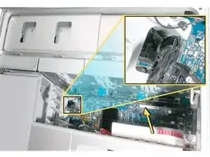
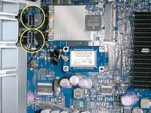
    • Disconnect the booster cable(s) from the logic board.

    • Release the small locking clip at the front of the card’s logic board connector by pushing the clip up toward the media shelf.

    • Holding the card by the top corners, gently pull up the card and remove it from its expansion slot.

    • If you are replacing a booster cable with a new one, disconnect the cable from the card.

  4. RH6LZDVqt6Kau2m5
    • Replacement Note for Card Using One Booster Cable: Be sure to connect the card’s booster cable to the correct auxillary power connector on the logic board. Connect the booster cable for a card in PCI slot 1 to the lower connector. Connect the booster cable for a card in PCI slot 2 to the upper connector.

    • Replacement Note for Card Using Two Booster Cables: Connect both cables to the two auxillary power connectors.

    Estoy buscando el cable de alimentación de la tarjeta gráfica, pero no lo consigo alguna idea de dónde lo podría conseguir?

    Videos premium -

  5. VEPsvWfTg4xTwkeY
    • The procedure to remove the graphic cards is the same for PCI Express Cards for exception of minor card differences.

    • Important: Combined maximum power consumption for all four PCI Express slots must not exceed 300 W.

  6. tDWYERvKSToJqiKZ
    tDWYERvKSToJqiKZ
    dXMjc5ajdKueg1li
    • Remember to check that all the PCI Express cards have been removed and properly stowed.

    • Note: The heatsink cover is held in place by a number of tabs and magnets on the underside of the cover. You must release the tabs before you can remove the cover from the enclosure.

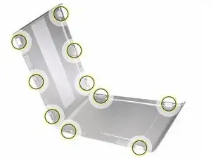
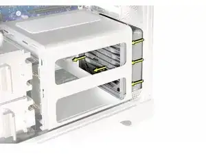
    • Place the fingers of one hand under the lip of the heatsink cover nearest the logic board. Lift the lip slightly toward the media shelf to release the tabs and magnets under the top face of the cover.

    • With your fingers still under the cover’s bottom lip, lift the cover straight up to release the remaining tabs and magnets under the front face of the cover

    • Remove the cover from the enclosure.

    You don’t need to place the fingers under the lip of the heat sink cover nearest to the logic board. It is much easier to use a pry tool and slide it through from front to the back. It will release the tabs very easily.

    andrenozawa -

    %#*@ this was a horrible guide until I read your comment. The model I’m pulling apart has no magnets holding it together

    placebomessiah -

    This section of the guide does not apply to the 2006 A1186 (EMC 2113) MacPro 1,1. In this model (that I'm trying to disassemble in front of me, now), the heat sink cover is partly under the RAM cage, so it cannot come out before the RAM cage. The linked guide above seems to reference this fact.

    Is there a way to submit an alternative version of this section for the models in question?

    DavidM -

  7. sGTT2CVRrfoQt6qH
    • Replacement Note: When reinstalling the processor heatsink cover, make sure the tabs on the underside of the cover align with the slots directly below them. (The slots are on the front fan and memory cage on either side of the heatsink cover.)

  8. Rjrpjev2ueUsITYf
    • Additional pairs of 1 GB, 2 GB, or 4 GB FB-DIMMs can be installed in the open DIMM slots. Maximum memory is 32 GB.

    • DIMMs must be installed as pairs of identical size and type, from the same vendor. Use the provided illustration, like-colored DIMMs must match.

    • DIMMs for Mac Pro (Early 2008) must fit these specifications:

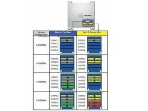
    • 800 MHz, DDR2, FB-DIMMS

    • 72-bit wide, 240-pin modules

    • 36 memory ICs maximum per DIMM

    • Error-correcting code (ECC)

    • Important: For proper operation of Mac Pro (Early 2008) computers, Apple recommends using only Apple-approved Mac Pro (Early 2008) FB-DIMMs

  9. VnKR2VWxcX2JUlnZ
    • Warning: Always wait 5–10 minutes for the computer to cool down before you remove or install memory. The DIMMs may be very hot.

  10. Ie1JdX2jWLRLICgI
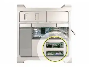
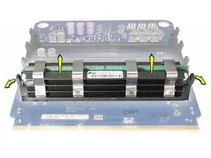
    • Holding the memory riser card by the two finger holes, pull it out of the memory cage and place the card DIMM side up on a soft, clean cloth.

  11. bTJwrPNXj5NVPZFB
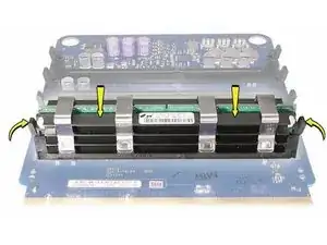
    • Open the ejectors on the DIMM slot by pushing them out to the sides, and remove the DIMM from the riser card.

  12. I3qiIZLANP5yFfUK
    • Replacement Note: Align the DIMM in the slot on the riser card and push both ends of the DIMM down until the ejectors snap back up into place.

    • Warning: FB-DIMMs carry heatsinks on either side of the DIMM. Never attempt to remove the heatsinks from the DIMMs. Doing so could damage the DIMM.

  13. PKDoSNSkjpRClJNX
    PKDoSNSkjpRClJNX
    V2TkxPIDVMAxNwxV
    • Disconnect the rear fan cable from the logic board.

    The rear fan cable on the 2006 EMC 2113 is at the bottom of the system board, inside of the RAM cage

    DavidM -

  14. ZxoWjhLraXNErpvy
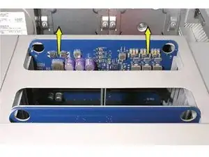
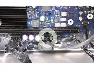
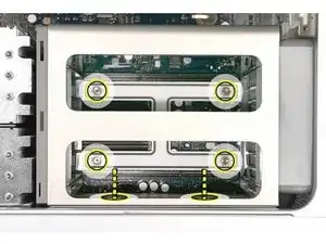
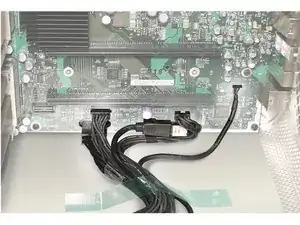
    • Using a long-handled, magnetized #1 Phillips screwdriver, loosen the four captive screws that mount the memory cage to the logic board.

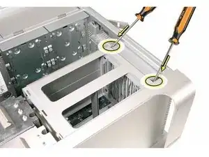
    • Rotate the computer so that it is standing vertically. Using a magnetized short-handled or right-angled jeweler’s #1 Phillips screwdriver, carefully remove the two short screws that mount the memory cage to the bottom panel of the enclosure.

  15. qbCEqsPMPFToOlIQ
    • Note: To remove the memory cage and fan, you must first slide the fan partway into the cage. The fan is held in place by three latches, which you must release before sliding the fan.

    • Using your forefinger, reach below the fan and release the latch nearest the logic board.

    this doesn’t exist on my Mac Pro 1,1

    michealedson -

  16. ZPAEIwps36WGAAJl
    • Using a flat-blade screwdriver, release the two latches nearest the front of the computer.

    I can see around this, doesn’t exist on my Mac Pro 1,1

    michealedson -

  17. aVIKJKannDLEirhI
    • Slide the rear fan into the memory cage.

  18. Ae2beNaxuZRBGba2
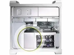
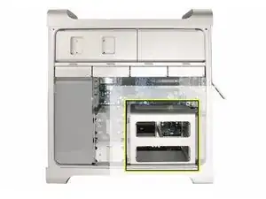
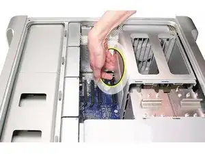
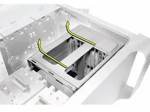
    • Slide the memory cage and fan toward the power supply far enough that the cage clears the bottom edge of the enclosure. Then lift the memory cage and fan out of the enclosure.

  19. WyI2lg1NlRsOYvtg
    • Replacement Note: If you are installing a new fan in the memory cage assembly, rotate the fan into the cage as illustrated. Also note carefully the orientaton of the fan in relation to the cage.

  20. vMDdWCPbPb4TGGQL
    vMDdWCPbPb4TGGQL
    oYKkTWh2qUwaTIWD
    • Important: Before you install the cage in the enclosure, the fan should always be inserted partway into the cage.

    • Replacement Note: Before installing the memory cage and fan, make sure all logic board cables below the cage are out of the way so that the cage sits properly and the cables are not pinched or damaged when you tighten the screws.

    • Replacement Note: To install the memory cage and fan, maneuver the cage into position in the enclosure. Tighten at least two of the captive mounting screws. Then slide the fan toward the back panel, until you hear it snap into place.

Conclusion

To reassemble your device, follow these instructions in reverse order.

Joshua Byrne

Member since: 03/05/13

7635 Reputation

0 comments