Introduction
Tools
-
-
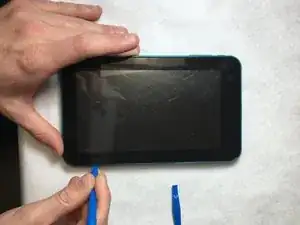
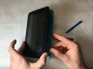
Insert plastic opening tool at the corner of the screen, in between the back case and the front.
-
Volume buttons will fall out during removal.
-
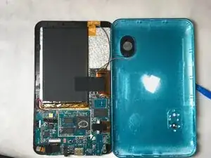
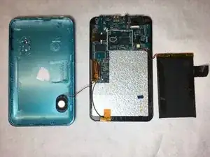
When opening up the case, have the I/O ports facing you and turn the back case towards the right. There is a short wire connecting the speaker to the logic board.
-
-
-
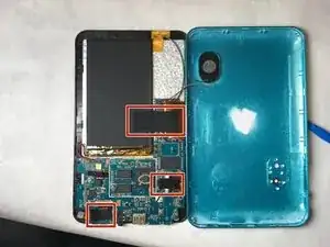
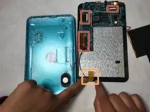
Carefully pry the tape from the battery, the bottom left chip, and the ribbon cable towards the bottom-right of the board. The bottom left has a little silver square component that must also be unclipped and untaped.
-
The battery is glued to the back of the screen; therefore pull the battery off of the back with caution. There will be resistance but that's okay.
-
-
-
Gently unclip the data cable retainers and remove the wires from the junctions.
-
Peel the tape off the wire near the bottom of the case.
-
-
-
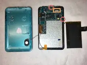
Remove the two 4mm screws (circled in orange) with a 00 Phillips head driver.
-
Unclip the black plastic retainer near the data port. The PCB should now be able to be gently pulled off.
-
-
-
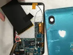
Make contact with the battery terminals with the hot tip of the soldering iron for a few seconds while slowly pulling the wire away.
-
To reassemble your device, follow these instructions in reverse order.
