Introduction
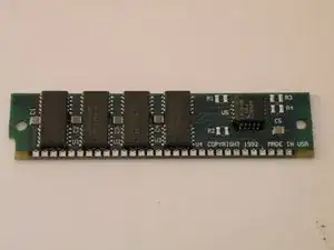
The Macintosh IIsi uses 4 30-Pin RAM SIMMs, installed in pairs of two for a maximum capacity of 65MB (4X16MB + 1MB). It has 1MB of RAM soldered to the logic board.
Tools
-
-
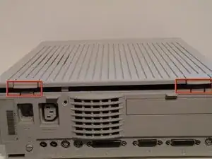
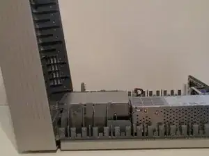
Now lift these two clips, and slowly pivot the case up.
-
You can now seperate the top of the computer from the rest of the machine.
-
-
-
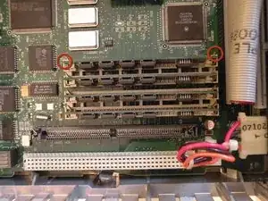
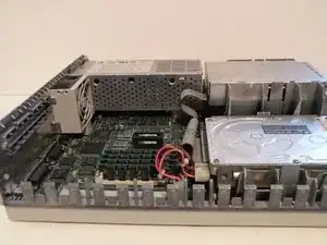
The IIsi uses 4 30-Pin SIMMs (Installed in pairs of 2) for a maximum ram capacity of 65MB. It has 1MB soldered to the logic board as well.
-
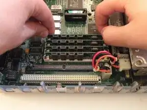
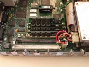
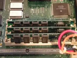
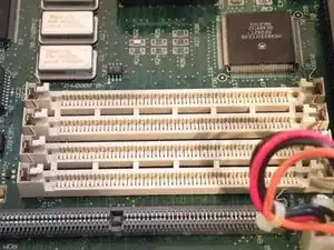
Start with this SIMM. Push these 2 metal tabs outward, then push the ram forward. It can then be lifted out. You have to remove the SIMMs in order, starting with the one you just removed. You can then work your way through all of them.
-
Conclusion
To reassemble your device, follow these instructions in reverse order.