Introduction
Here is the guide for the power board removal. It will be necessary to discharge the CRT prior to that. Please follow the guide for that to prevent any personal injury. Most common reason for the removal of the power board, would be a repair or recap due to its age.
-
-
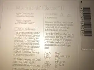
Here is one of the vintage computers in my possession. It is a Macintosh Classic II M4150. Apple considers this obsolete and " information about these products is no longer updated as of 9/1/98 "
-
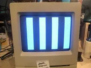
On powering it up, It originally greeted me with a checkerboard pattern that quickly converted into this pattern. The checkerboard pattern is/was commonly caused by bad Ram memory. Considering the age of this computer, leaking capacitors are a strong possibility. Time to check.
-
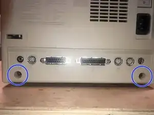
The cover is held in place by four (4) T-15 screws. Two (2) on the bottom
-
-
-
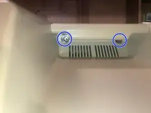
and two (2) under the top (handle)
-
The bottom ones are easy to remove
-
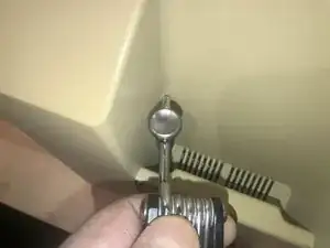
The top ones are a bit of a challenge due to the depth of the holes.
-
-
-
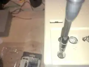
There was just not enough room to get a good grip on the driver.
-
Luckily this iFixit driver has a hole on the top part. I used a tool to gain some mechanical advantage. While applying downward pressure on the driver, turn the tool to the left to loosen the screw
-
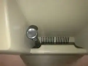
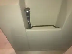
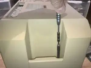
Once loosened, the iFixit extension that came with my set, works perfectly to remove the screw,
-
-
-
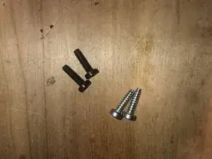
Here are the four (4) screws. The two bottom screws are M4X15mm The top screws are those typical found in plastic to sheet metal joints.
-
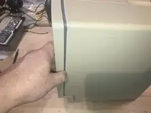
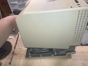
With the screws removed the cover will slide off.
-
BEst practice is to lay it down and pull the case straight up. It may take some force due to the tight fit and years of storage etc.
-
-
-
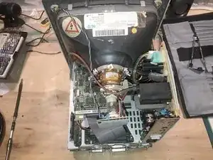
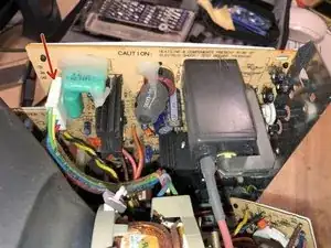
Here is what the inside looks like.
-
Power supply (Sweep Board)
-
Flyback Transformer
-
Video card
-
CRT
-
SCSI Hard drive
-
Hard drive on top with the Floppy drive on the bottom
-
-
-
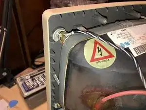
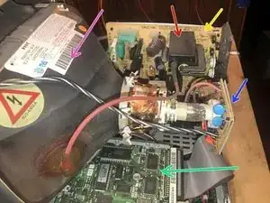
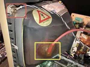
Ground screw
-
Anode Cap
-
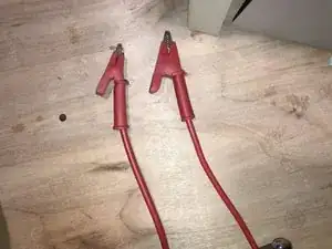
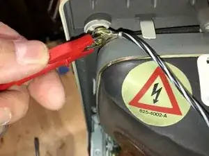
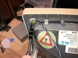
I use a test lead I had which has Alligator clips or either end. Worked perfect for this. A piece of insulated electrical wire 18 gauge AWG (or similar) will work for this as well.
-
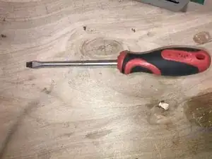
Next is a Flat Tip screwdriver that must italic texthave an insulated handle. No substitution allowed!
-
-
-
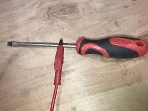
Connect one end of the electrical wire to the flat tip screwdriver
-
Connect the other end of the wire to the grounding screw
-
Not the sound of an explosion or anything as climactic, but definitely a cracking sound. If your CRT was discharged, maybe because it was unplugged for a awhile etc., you will not hear anything.
-
-
-
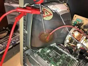
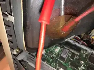
I susually make sure that the screwdriver did touch the metal and using the same precautions as before, move it on the metal for the Anode. Just to ensure it did make proper contact. Usually I wait a minute or two before withdrawing the tool.
-
The CRT is now discharged.
-
-
-
Here is the grounding screw. It also holds the video board ground.
-
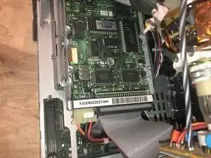
Here is the video board
-
Remove the T15 ground screw
-
-
-
To rmove teh video board, pull it stright back. tehre might be some glue/sealant type that you need to remove first. This is different from computer to computer. So, check for that before just pulling on it. Should this be on your computer, carefully use a sharp blade to cut that sealant.
-
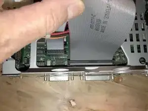
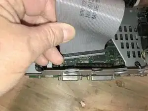
Next is the SCSI HDD Ribbon cable which needs to be removed.
-
-
-
No lock on it but it is a 50 pin cable and it is rigid. Takes a bit of force to pull it straight up
-
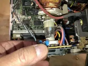
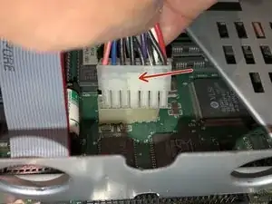
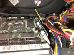
The reason for the SCSI HDD Cable removal is the logic board power cable
-
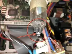
To remove it, simply push on the tab and pull it straight up
-
-
-
Remove the HDD Power cable
-
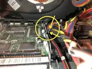
On the HDD caddy is a metal clip that functions as a wire holder for the logic board power cable.
-
Bend it slightly away from the caddy to free the wire
-
-
-
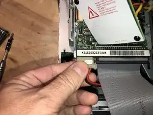
One more cable to be removed is the Yoke cable
-
Simply pulling on it will remove it. No lock on this
-
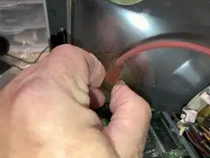
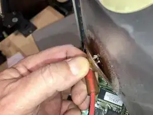
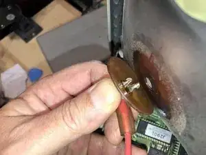
Now its time to remove the Anode. Grab it firmly
-
-
-
and squeeze (lots of force with your thumb downward. That should free up the top notch
-
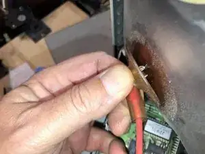
As you are squeezing and freeing to top notch, tilt the wire at an angle downward
-
and then lift it out. It does take considerable force to squeeze that wire. Do not use any pliers etc, since that may damage the insulation. That may lead to shocking experiences later.
-
-
-
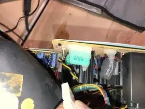
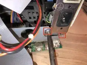
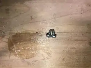
Now remove the two (2) Philips sheet metal screws
-
They are 3mm in diameter and 8mm long
-
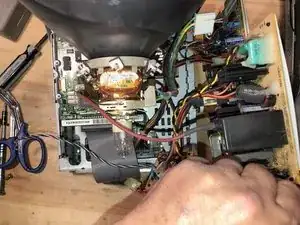
Now let's move the power board to the right of the chassis. Do those gently since there is still one cable attached
-
-
-
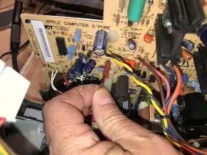
Remove the fan from the power board. The connector has a small tab that needs to be lifted to remove the connector
-
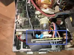
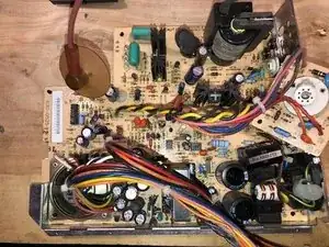
Now the board can be removed without difficutlies. this board looks like it has been recapped. Or Apple used some really high quality capacitors on the original....Nah. I don't think so. Anyhow, it's a clean board with no damage from leaking capacitors etc.
-

To reassemble your device, follow these instructions in reverse order.
