Introduction
This guide shows the removal of the Logic board. Straightforward with no hidden or proprietary screws.
Tools
-
-
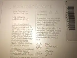
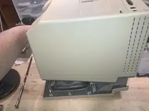
Here is one of the vintage computers in my possession. It is a Macintosh Classic II M4150. Apple considers this obsolete and " information about these products is no longer updated as of 9/1/98 "
-
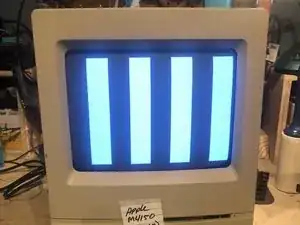
On powering it up, It originally greeted me with a checkerboard pattern that quickly converted into this pattern. The checkerboard pattern is/was commonly caused by bad Ram memory. Considering the age of this computer, leaking capacitors are a strong possibility. Time to check.
-
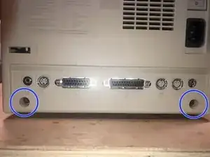
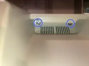
The cover is held in place by four (4) T-15 screws. Two (2) on the bottom
-
-
-
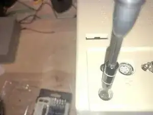
and two (2) under the top (handle)
-
The bottom ones are easy to remove
-
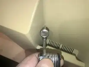
The top ones are a bit of a challenge due to the depth of the holes.
-
-
-
There was just not enough room to get a good grip on the driver.
-
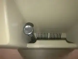
Luckily this iFixit driver has a hole on the top part. I used a tool to gain some mechanical advantage. While applying downward pressure on the driver, turn the tool to the left to loosen the screw
-
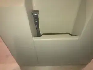
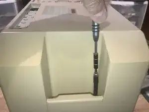
Once loosened, the iFixit extension that came with my set, works perfectly to remove the screw,
-
-
-
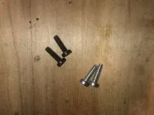
Here are the four (4) screws. The two bottom screws are M4X15mm The top screws are those typical found in plastic to sheet metal joints.
-
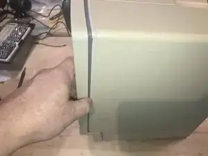
With the screws removed the cover will slide off.
-
BEst practice is to lay it down and pull the case straight up. It may take some force due to the tight fit and years of storage etc.
-
-
-
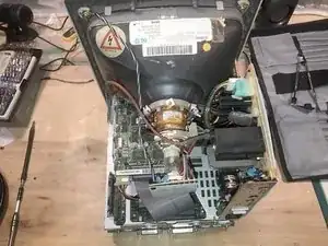
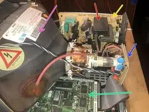
Here is what the inside looks like.
-
Power supply (Sweep Board)
-
Flyback Transformer
-
Video card
-
CRT
-
SCSI Hard drive
-
Hard drive on top with the Floppy drive on the bottom
-
-
-
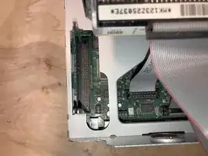
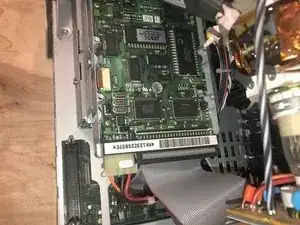
If your Classic II has the memory expansion board installed, it will be in this slot. It will need to be removed.
-
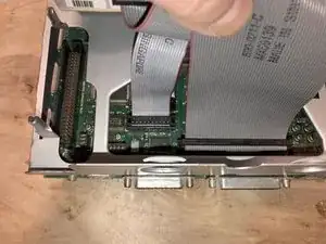
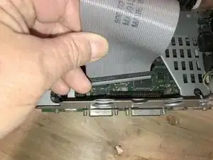
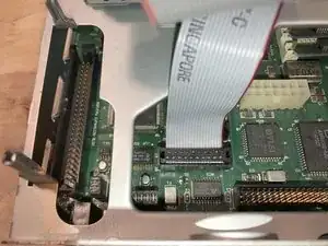
Next is the 50 pin SCSI HDD cable. These cables feel heavier and are more rigid than the IDE cables used in 90's
-
Pull the cable straight up. It may require some force, but there are no locks etc. to be removed. Just pull.
-
-
-
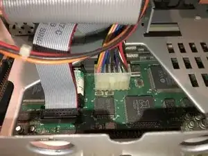
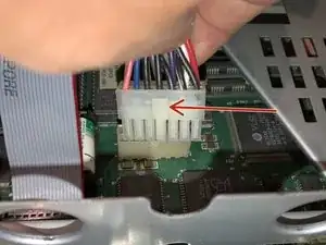
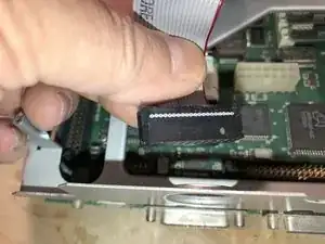
Next is the logic board power cable.
-
Pressing on the plastic tab will release the lock. Pull the cable up to remove it
-
Here is the Floppy drive cable. Red stripe always connects to pin one (1) on the connector
-
-
-
Just pull the cable out of its connector. No locks on this one either.
-
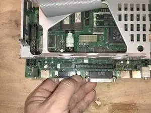
Next grasp the logic board by its edge and pull it out of the chassis
-
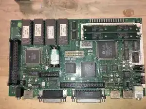
Here is the complete logic board. Battery and RAM modules clearly visible. Luckily no leaky battery. The board has some dust and shows some contamination. Overall it is in good condition for an almost 30 year old piece of electronics.
-
To reassemble your device, follow these instructions in reverse order.
