Introduction

Use this guide to replace a broken left clutch hinge.

  1. qPsGdXwUZZBT6RJa
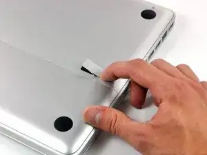
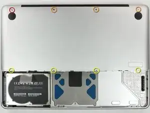
    • With the case closed, place the Unibody top-side down on a flat surface.

    • Depress the grooved side of the access door release latch enough to grab the free end. Lift the release latch until it is vertical.

    This is not a a1278 unibody MacBook Pro. A1278 MacBooks backs are one solid metal piece not two separate pieces. This guide is for a different MacBook Pro.

    Brad Burgeson -

    This guide isn’t for a pro; it’s a MacBook unibody.

    Nicholas -

    So, it turns out that Apple used the model code A1278 for quite a few different Mac models, including both Pro and non-Pro versions! This guide is for the non-Pro Macbooks. There’s also one for the Pro models with the same A1278 identifier.

    tempelmann -

  2. Pf4wGUpXWyJ3tAfH
    • The access door should now be raised enough to lift it up and out of the Unibody.

  3. WkwQip2DfR1iJLMX
    • Be sure the access door release latch is vertical before proceeding.

    • Grab the white plastic tab and pull the battery up and out of the Unibody.

    Great tutorial ! great step !

    Leo Etcheverry -

    Even though it’s specifically stated, you have to make sure the access door latch is vertical or the battery won’t be removable.

    Henry Kim -

  4. mgYUuNTR1BjI1A6i
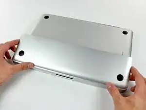
    • Remove the following eight screws securing the lower case to the chassis:

    • One 3 mm Phillips screw.

    • Three 13.5 mm Phillips screws.

    • Four 3.5 mm Phillips screws.

    On my model, it seemed the top-left was 3.5mm and the bottom 4 were 3 mm.

    Jim -

    Make sure you have a good quality Phillips screwdriver. Mine had removable tips and had a small play at the connection. As a result I didn't have a good feel and damaged my screws (those securing the fan and the top left in step 23). Game over for me installing new thermal paste...

    Be very carefull with your screws! Especially those on the inside.

    Nickolas Michelinakis -

    You can get away with a Phillips #00 for many of the screws involved but the 4 at the bottom case split are likely to strip if you don’t use a JIS #00 or, in a pinch, a Phillips #000.

    Bill Cole -

    I used the Phillips #00 tip from my Pro Tech Toolkit, and it worked well enough. But yes, maybe #000 might have been better on the lower row of screws. Note to myself: Always read the comments first.

    Les Kitchen -

    When replacing these screws, the order to replace them in is as follows:

    1, Top left

    2. Top right

    3. Top center-left

    4. Top center-right

    5. Bottom center-right

    6. Bottom center-left

    7. Bottom right

    8. Bottom left

    I hope this information is helpful.

    facebook -

    I followed my usual process of putting in all the screws loosely, then tightening them gradually in distributed pattern, to help ensure that the panel settles in place evenly. But maybe some orders are better.

    Les Kitchen -

  5. EZrPgfOVIaaIsXLR
    • Using both hands, lift and remove the lower case off the upper case.

    Thanks for the guide!

    It's implicit in the two photos, but worth mentioning because it blocked my progress in this step for a bit: You have to put the release latch back into its horizontal, closed position before you can lift off the lower-case panel.

    Les Kitchen -

  6. UnfTVKa4kGgLhmpS
    • Disconnect the camera cable by pulling the male end straight away from its socket.

    • Be careful not to pull up on the cable as you remove it from the socket.

    Be EXTREMELY careful when removing and re-inserting the 'camera' cable. The contacts can be easily bent beyond repair if you try to force it back in. Damaging this cable at this connection or near the display may disable your ability to use your iSight camera, AND both your Bluetooth and WiFi. I had to pay apple $300 to replace the entire display assembly because one prong was faulty, causing my WiFi card to not be recognized.

    seanheff17 -

  7. xORcdpjYmZYWrNAc
    xORcdpjYmZYWrNAc
    Dm5qBsfLdS1OVoer
    • De-route the camera data cable from the channel in the optical drive.

    Although I ordered the screen for an A1278 MacBook Unibody Aluminum, the screen glass was marked as a MacBook Pro. The iSight/WiFi /BT cable was about an inch longer than the Macbook one and took a bit of creative re-routing, but everything works fine.

    tjod -

    has it got the airport and bluetooth modules built in separately in the display assembly as in the macbook late 2008 and mbp mid 2009?

    fericcio -

  8. 6FQppPtEshmRXyuq
    6FQppPtEshmRXyuq
    HLtfrIbButKCKkVh
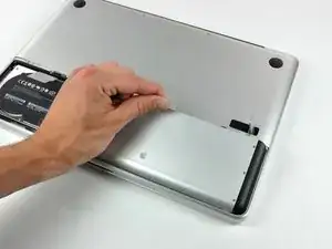
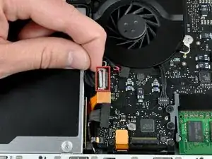
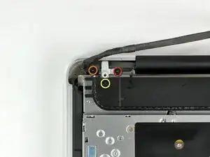
    • Remove the following screws securing the camera data cable and right speaker to the upper case:

    • One 9.9 mm partially threaded Phillips screw

    • One 9.6 mm threaded Phillips screw

    • One 4 mm Phillips screw

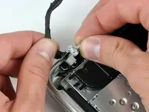
    • Slide the camera cable bracket out from under the subwoofer and remove it from the computer.

    • The iSight cable has an eyelet through which passes the left-most screw in these pictures.

    "orange" is the short one, that goes in the middle ;)

    Riesling -

    My model has different bracket, you need to remove the subwoofer first

    Andrea Ghensi -

    1. With my Laptop, the left screw was partially threaded, not the right one. 2. Before removing the camera cable bracket, I needed to unscrew the subwoofer.

    Edgar Fuß -

  9. dUR61OdDgcqO6ZhU
    dUR61OdDgcqO6ZhU
    CVDUNKbRkXIbkxIB
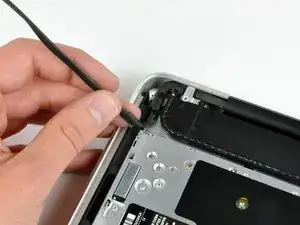
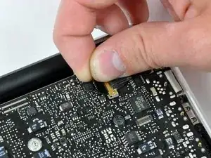
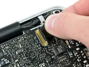
    • Grab the plastic pull tab secured to the display data cable lock and rotate it toward the DC-in side of the computer.

    • Pull the display data cable connector straight away from its socket.

    • Make sure to pull the connector straight away and not straight up from its socket.

    i can't understand what I need to do in this step, I'm afraid with this step, i think i can "hurt" my mac and i don't want to do that, anyone knows what i need to do?

    Thanks

    Lucas Borges -

    There is a steel 'latch' that flips over from the left side of the connector, to the right side. After you flip this latch over, the cable will easily slide out.

    madmaxmedia -

    as I pulled the monitor cable out of the bracket after flipping the lock over one side of the bracket broke loose. Now the monitor will not turn on. Can anyone help?

    boldtu -

  10. KX4fAOE6kkiQnPIE
    KX4fAOE6kkiQnPIE
    ocp6hFJoAXBGxWtU
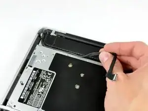
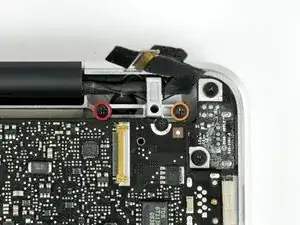
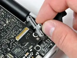
    • Remove the following two screws from the display data cable bracket:

    • One 7 mm Phillips screw.

    • One 5 mm Phillips screw.

    • Lift the display data cable bracket out of the upper case.

    Note for Step 10 during reassembly: Be careful when replacing the screw for the display cable bracket closest to the magnetic power cord receptacle. The interior magnet might attract the screw causing the screw to get pulled under the DC power circuit board which might then require that you disassemble things again to retrieve the screw.

    wintermute -

  11. JZwrRypptntvcRW6
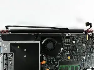
    • Remove the two outer 6 mm Torx screws securing each side of the display to the upper case (4 screws total).

    Hey guys, with these older models Do Not interchange different colored LVDS cables. Note the connector here is gold, do not use a silver connector on a gold one or vice versa. I fried a logic board this way on an A1278. Note that the core i7 lvds connector is different than the core i5.

    rjpoirier_nb -

    I never thought that I’d be required to use PB Blaster to remove computer screws. Had to use two tiny drops for each screw, letting it soak in for 20 minutes or so. The display screws, coated with blue thread lock, did not want to budge. I was so fearful that I would strip them using a T-6 driver. Ended up using a 1/4” drive ratchet with a T-6 bit, pressing down firmly and blocking the MacBook from turning with my elbows. I’ve had a lot of experience doing this kind of work, but wow!

    randy3833 -

  12. 3hMFv5xctPAx6bqU
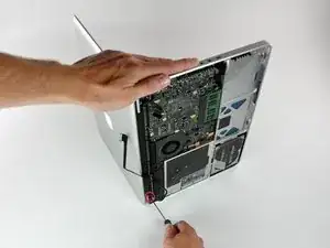
    • Open your MacBook so the display is perpendicular to the upper case.

    • Place your opened MacBook on a table as pictured.

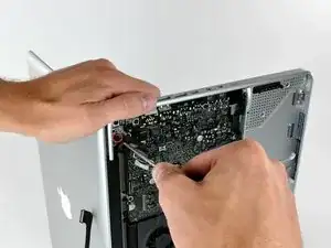
    • While holding the display and upper case together with your left hand, remove the 6 mm Torx screw from the lower display bracket.

  13. UENnAHrYGcqTUVrT
    • Be sure to hold the display and upper case together with your left hand. Failure to do so may cause the freed display/upper case to fall, potentially damaging each component.

    • Remove the last remaining 6 mm Torx screw securing the display to the upper case.

  14. X6xvVBK6giPdMK5I
    X6xvVBK6giPdMK5I
    YZXiaPDuWVTfRJvE
    qOX2lhZEtxKWCLNr
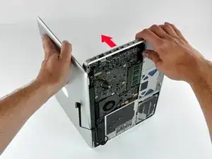
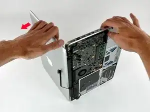
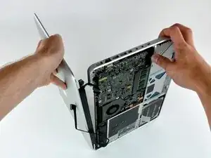
    • Grab the upper case with your right hand and rotate it slightly toward the top of the display so the upper display bracket clears the edge of the upper case.

    • Rotate the display slightly away from the upper case.

    • Lift the display away from the upper case, minding any brackets or cables that may get caught.

  15. wgRoBlTmHppiPiwQ
    wgRoBlTmHppiPiwQ
    HCyfQLHZqYvrKLtF
    • Grab the clutch cover as shown and slide it toward the right side of the display.

    • It should move about 1/4" and stop. Don't force it beyond this point.

    i've found this impossible to get back on correctly.

    i cant get the plastic to slide back that 1/4" it needs to fit properly

    Does anyone know any tricks? :(

    Ashley Berthon -

    imagine the monitor upside down and the screen facing away from you. You have to put the cover over to the right of where it goes about an inch or 2 and it will go in, then, slide it left to lock it into place

    stdonato -

    I was replacing a clutch cover that had cracked into a few pieces. I found the replacement didn’t slide to the left on installation. On further investigation I found the tabs from the old one were broken off inside where the cover slides. Once they were removed the install wen much better.

    I found my replacement cover on Amazon.ca in case someone needs a Canadian source.

    Dean Landry -

  16. Vns5bAdNqAak5lWZ
    Vns5bAdNqAak5lWZ
    EFvH5PPgXLgPSsXL
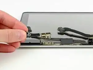
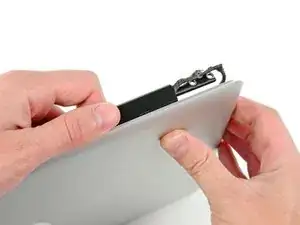
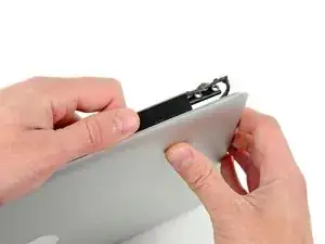
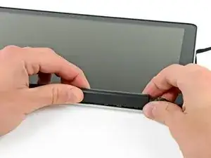
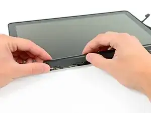
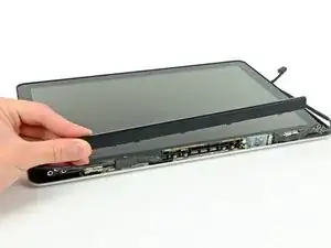
    • Gently rock the clutch cover back and forth on its long axis while pulling it away from the display.

    • Do this action along the length of the clutch cover until you can lift it off the framework attaching it to the display.

  17. iegYVqjNQuaLTiBw
    • Remove the clutch cover from the display.

    The flat face goes on the bottom edge of the display. The display and wifi cables must be routed below the hinges in the display, that is, closer to the bottom edge of the display.

    Robert Rossi -

  18. kE4JENWqndNV2Tof
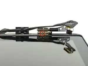
    • Remove the single 5.2 mm T6 Torx screw securing the left clutch hinge nearest the display glass.

  19. URs6MLTGmU2TcydI
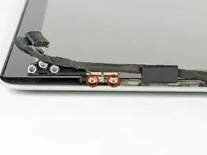
    • Remove the remaining two 5.2 mm T6 Torx screws securing the left clutch hinge to the display.

  20. ocCA65G6EC36FWSL
    • Remove the left clutch hinge from the display.

Conclusion

To reassemble your device, follow these instructions in reverse order.

Walter Galan

694047 Reputation

0 comments