Introduction

  1. fL4HNo1lPsrDb1rO
    • Before disconnecting the camera cable, a small plastic retainer stuck to the logic board must first be moved out of the way.

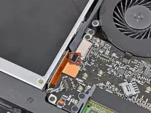
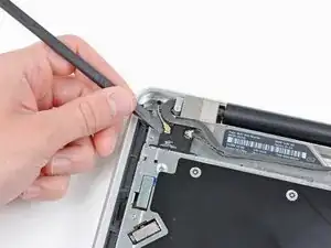
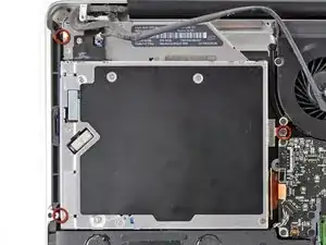
    • Use the tip of a spudger to push the small plastic cable retainer away from the camera cable socket for enough clearance to remove the camera cable.

    This step does not apply to the A1297.

    Katherine Williams -

    Yes, as Katherine says, this does not seem to apply to the early 2011 model. The camera cable is instead attached to the logic board in the corner between the fan and the optical drive. You pull it out horiontally (and carefully, perhaps with help from the spudger tip at the "wings" on the end of the cable.

    Lami -

  2. xNVDxnvPenQ1WIjQ
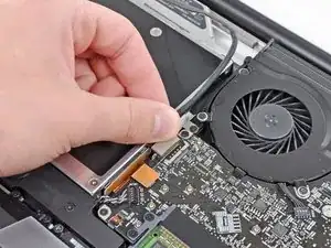
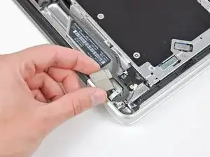
    • Pull the camera cable toward the optical drive opening to disconnect it from the logic board.

    • The camera cable socket is very fragile. Do not apply any upward force to this socket, as it may break off the logic board. Pull the camera cable parallel to the face of the logic board.

    • For Late 2011 models, the camera connector plugs straight down into the motherboard—to remove this connector, gently lift it straight up.

    My A1297 looks very different from this picture. The camera cable is not affixed with any plastic piece, it was a small blade connector that was at the top left corner of the mobo. It is removed by pulling it horizontally from the socket. It is my least favorite type of cable connection and the one most likely to be bent in the process (or the socket, be careful).

    maccentric -

    My mid2010 1297 was also different. Camera cable is per "step 7" here (http://www.shareyourrepair.com/2014/11/h...). Very very delicate.

    scottbernardis -

  3. 4yxJD4wJRo14Bh5s
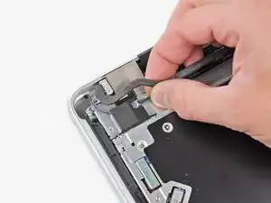
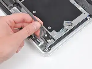
    • Carefully pull the Bluetooth cable toward the fans to disconnect it from the Bluetooth board.

    • Pull the cable parallel to the face of the optical drive.

    Once again, this step, and the rest that follow regarding the bluetooth board, bears no resemblance to my A1297. Luckily, it looks like things have been made simpler. Remove the camera cable from it's socket, the bluetooth cable (flat, black, just shy of .5" wide), and the DVD cable from their sockets. Remove the screw from the top right side of the black plastic piece that holds the bluetooth board and all the skinny black cables. Remove the screw at the top of this piece that fastens to the hinge (look for the shiny metal). Then just lift that piece out of the way, remove the 3 screws holding the DVD in place, and you can pull the drive out (I just grab it by the orange cable and pull it out, but that's probably not the preferred method).

    maccentric -

    Again, also mid 2010 A1297, the large flat cable crosses the drive. Remove on logic board end by prying carefully "UP" away from the board. Step 8 here: (http://www.shareyourrepair.com/2014/11/h...)

    scottbernardis -

    I was switching the optical drive from my non-functioning 17" to my 15" (same early 2011 MBP) and I was confused, as the arrangement looked almost exactly like the arrangement in my 15" machine rather than what is pictured here. So one can follow the instructions for the 15" MBP here on iFixit instead if you don't recognise what you see!

    Lami -

  4. dykEom62YREuoSyW
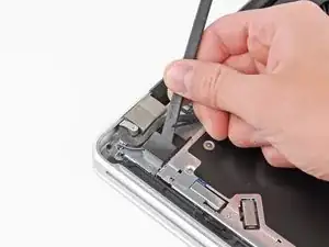
    • Use the flat end of a spudger to peel the thin plastic cover off the top and sides of the Bluetooth board housing.

    Is there any real need to remove these cables from the Bluetooth Board? Are you not able to simply conduct step 14 here instead, leaving cables in place, therefor not jeopardising integrity of the housing?

    Does the indicated Dual HDD housing replicate the holes found on the Optical Drive to allow this?

    Fletch Christian -

    mid 2010 A1297 again. Different configuration. I had a black plastic housing along this whole side. The large flat ribbon connects to it and I LEFT THE RIBBON IN PLACE on this housing. I removed 3 screws here to allow this black housing to be lifted off the drive and to the side, along with the camera line (held down by 3rd screw). When REPLACING this black housing after installation is complete, note there is a small tab on the disc slot side of the housing that needs to be inserted into a slot for correct placement. Then SKIP TO STEP 10 on this IFIXIT tutorial.

    scottbernardis -

    On the A1297, there is a 4” black bracket held by two screws. Remove those, a short and long one. The cable runs along the lower edge of the bracket and connects near the fan screw, near the optical drive connection. Remove that cable by print toward the optical drive in the direction of the cable, NOT UPWARDS.

    Katherine Williams -

  5. mMUpe3HjBQSGGtgh
    • Use the flat end of a spudger to pry the Bluetooth antenna connector up and off its socket on the Bluetooth board.

  6. 12YwqsCq22TxKYhC
    12YwqsCq22TxKYhC
    EmOuqEBZjJT6RmdS
    • If present, remove the small piece of EMI foam near the Bluetooth board.

    • De-route the camera cable from the slot molded into the Bluetooth board housing.

  7. KqKruKOGSOMiKPtS
    • Use the flat end of a spudger to pry the optical drive connector up and out of its socket on the logic board.

  8. GqN3KxB2rMQHLqCY
    • Remove the three 3.5 mm Phillips screws securing the optical drive to the upper case.

    • To remove the screw closest to the battery, it may be helpful to use a T6 Torx screwdriver to first remove the upper case bracket directly above it.

  9. NDUrggqg1qewMhDk
    • Remove the optical drive from the upper case, minding any cables that may get caught.

Conclusion

To reassemble your device, follow these instructions in reverse order.
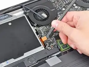
Andrew Bookholt

585795 Reputation

0 comments