Introduction
If your camera seems to be acting strange, it may be the fault of the camera cable. If you find that the Wi-Fi connection works only when the display is in a certain position, your camera/AirPort cable may be the culprit. Use this guide to replace a broken or damaged cable.
Tools
-
-
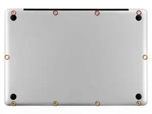
Remove the following ten screws securing the lower case to the upper case:
-
Three 13.5 mm Phillips screws.
-
Seven 3 mm Phillips screws.
-
-
-
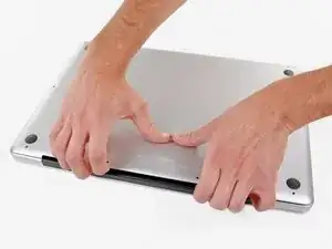
Wedge your fingers between the lower case and the vent, and lift upward to release the two clips holding the lower case to the upper case.
-
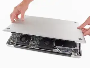
Remove the lower case.
-
-
-
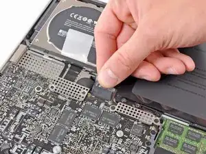
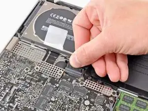
If present, grab the plastic tab attached to the battery connector and pull it toward the front edge of the device. For Late-2011 models the battery connector will not have a tab and is simply a plug that inserts straight down into the motherboard--to remove pry the plug straight up.
-
-
-
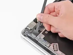
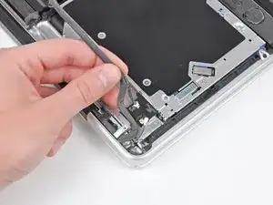
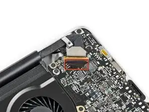
Use the tip of a spudger to push the small plastic cable retainer away from the camera cable socket for enough clearance to remove the camera cable.
-
-
-
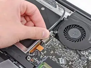
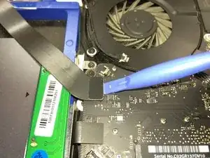
Pull the camera cable toward the optical drive opening to disconnect it from the logic board.
-
-
-
Carefully pull the Bluetooth cable toward the fans to disconnect it from the Bluetooth board.
-
-
-
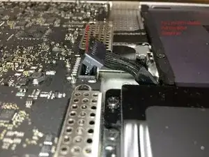
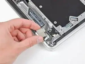
Use the flat end of a spudger to peel the thin plastic cover off the top and sides of the Bluetooth board housing. For late-2011 models check out the other picture because the connector location is in a totally different location.
-
-
-
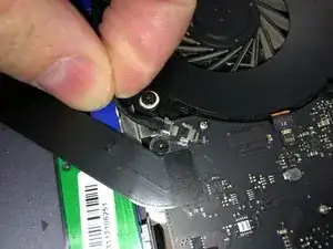
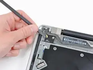
Use the flat end of a spudger to pry the Bluetooth antenna connector up and off its socket on the Bluetooth board.
-
-
-
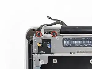
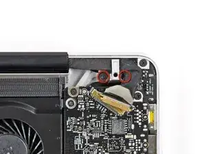
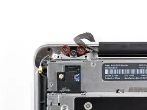
Remove the two 7.1 mm Phillips screws securing the camera cable retainer to the upper case.
-
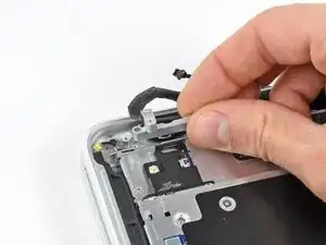
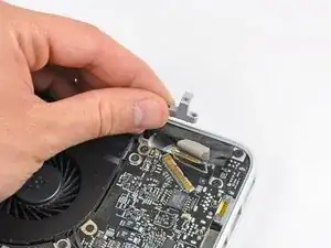
Remove the camera cable retainer from the upper case.
-
-
-
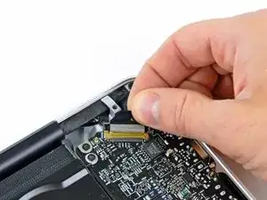
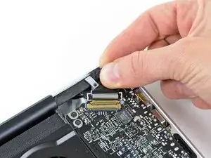
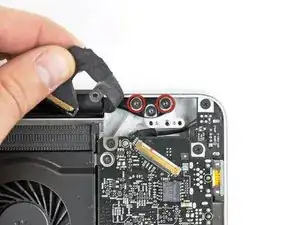
Lift the black plastic flap attached to the display data cable retainer and rotate it toward the DC-In side of the MacBook.
-
Pull the display data cable out of its socket.
-
-
-
Remove the two 7.1 mm Phillips screws securing the display data cable retainer to the upper case.
-
Remove the display data cable retainer.
-
-
-
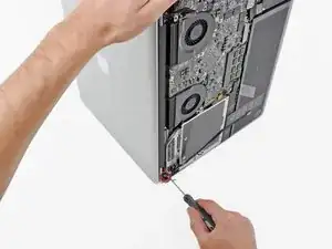
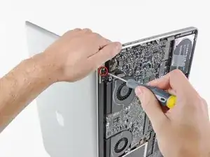
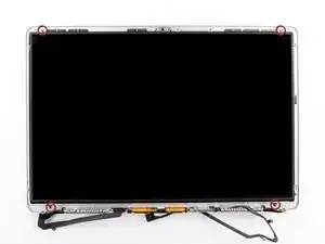
Remove the two outer 6.8 mm T6 Torx screws from each of the two display brackets (four screws total).
-
-
-
While holding the display and upper case together with your left hand, remove the remaining T6 Torx screw from the lower display bracket.
-
-
-
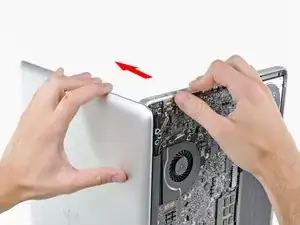
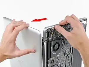
Grab the upper case with your right hand and rotate it slightly toward the top of the display so the upper display bracket clears the edge of the upper case.
-
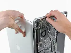
Rotate the display slightly away from the upper case.
-
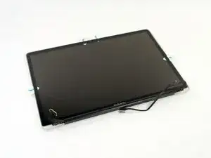
Lift the display up and away from the upper case, minding any brackets or cables that may get caught.
-
-
-
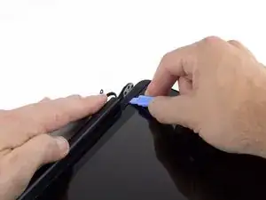
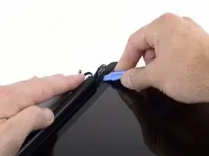
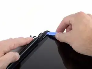
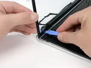
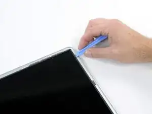
Insert a plastic opening tool underneath the black rubber gasket at the bottom left corner of the display assembly.
-
Gently pry the wide edge of the gasket up from the back case.
-
-
-
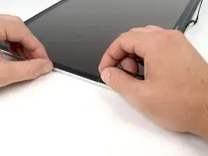
Starting with the freed corner, pull the left gasket off the left side of the display assembly.
-
-
-
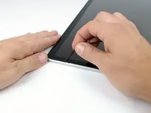
Continue pulling the display gasket off the display assembly down the right side.
-
Pull the gasket off the bottom edge of the display to completely free it and set it aside.
-
-
-
Before starting, be sure to clean the display glass with a lint-free cloth moistened with a mild solution; it will make the suction cup adhere better, and will make checking for dust on reassembly easier.
-
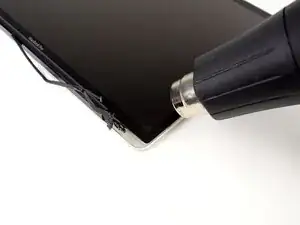
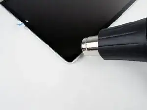
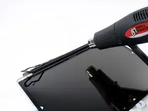
With the heat gun set to low, start by heating the outer black border near the upper right corner of the glass panel.
-
-
-
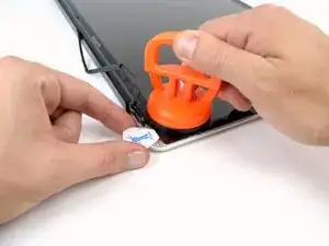
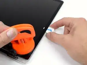
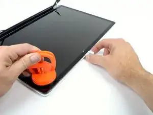
With the panel sufficiently heated, fasten a heavy-duty suction cup near the lower right corner of the display glass.
-
To attach the suction cups we sell, first position the suction cup with the movable handle parallel to the face of the glass panel. While lightly holding the suction cup against the glass, raise the movable handle until it is parallel with the other handle.
-
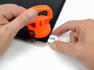
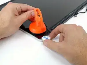
Gently lift the corner of the display glass enough to insert a guitar pick between it and the display assembly.
-
Use the guitar pick to gently pry up the adhesive securing the front glass to the display.
-
Pry up the glass panel along the right edge of the display up to the halfway point.
-
Leave the guitar pick in place halfway up the right side of the display and remove the suction cup.
-
-
-
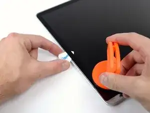
Use a heat gun to soften the adhesive under the display glass along the right and top edges of the display.
-
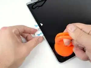
Attach a suction cup to the upper right corner of the front glass panel.
-
Pull up on the glass panel while you use a second guitar pick to separate it from the rest of the display assembly.
-
Continue working along the right edge of the front display glass until it is separated from the display.
-
-
-
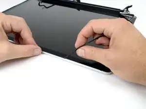
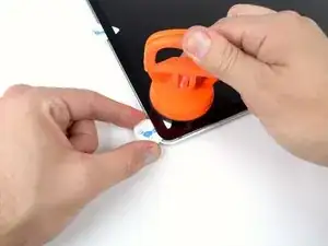
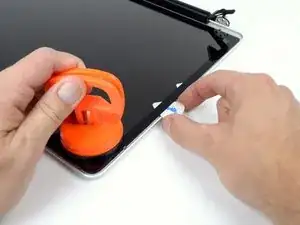
Work along the top edge of the display assembly, carefully prying the adhesive up with the guitar pick.
-
Stop prying about an inch before you reach the iSight camera. Leave the guitar pick in place and remove the suction cup.
-
-
-
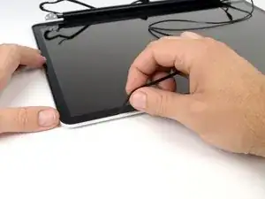
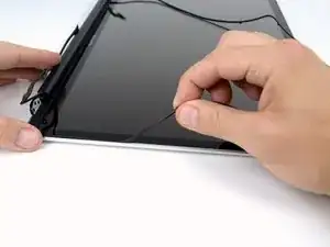
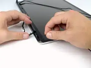
After prying up the three edges of the display glass, you should have four guitar picks resting underneath the panel, as shown.
-
-
-
With the heat gun set to low, heat the bottom edge of the display to soften the adhesive holding the glass in place.
-
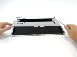
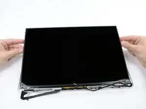
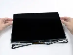
Slowly lift the top edge of the glass panel and gently rotate it out of the display.
-
-
-
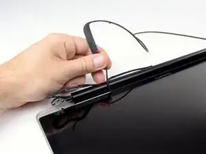
Lifting the left edge of the clutch cover, gently rock it back and forth on its long axis while pulling it away from the display.
-
Remove the clutch cover from the display, minding any cables that may get caught.
-
-
-
Lift one of the top corners of the LCD panel out of the rear bezel with a plastic opening tool.
-
Grasp the top corners of the LCD and rotate it upwards, slightly out of the display.
-
Pull the LCD toward the top of the display panel, freeing the screw tabs from underneath the rear display bezel.
-
-
-
Flip the LCD over and lay it face down, being careful to not put too much stress on the display cable.
-
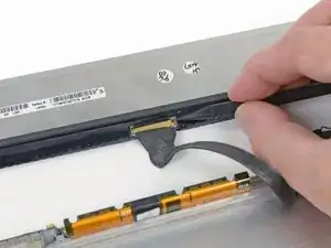
Peel the piece of tape covering the display data cable connector away from the edge closest to the LCD.
-
-
-
Use the tip of a spudger to flip up the thin steel retaining clip securing the display data cable to its socket on the LCD.
-
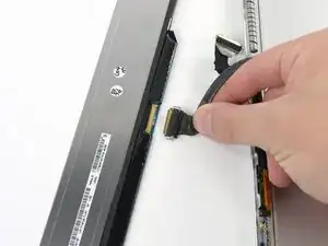
Pull the display data cable straight away from its socket on the LCD.
-
Lift the LCD out of the display assembly and set it aside.
-
-
-
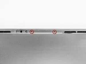
Remove the two 2.7 mm Phillips #00 screws securing the camera board to the rear display bezel.
-
-
-
Remove the 2.7 mm Phillips #00 screw securing the AirPort board bracket to the rear display bezel.
-
-
-
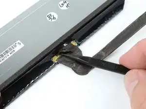
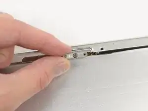
Move the AirPort board bracket towards the bottom of the display case with the tip of a spudger so that it does not block the AirPort board cable.
-
Use the tip of a spudger to disconnect the AirPort board cable by rocking it back and forth until it is free.
-
-
-
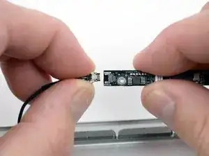
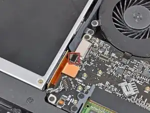
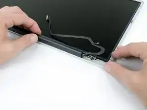
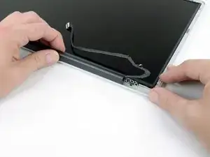
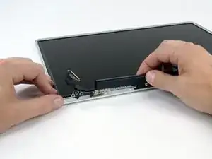
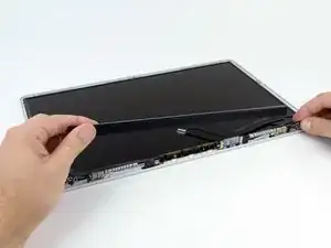
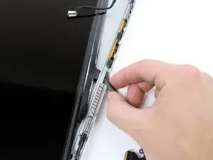
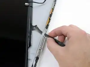
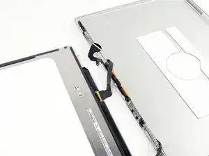
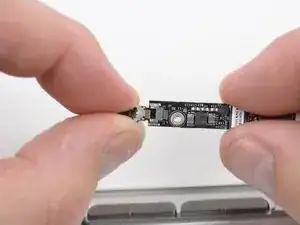
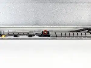
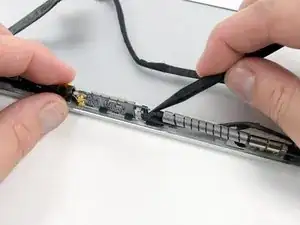
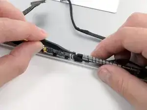
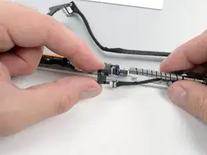
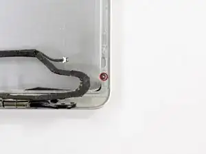
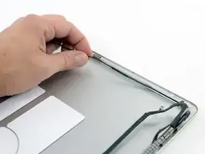
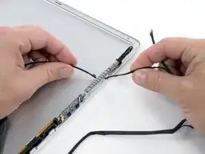
De-route the camera/AirPort cable from the display housing.
-
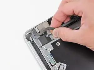
Carefully pull the camera/AirPort cable through the slot in the aluminum housing underneath the right display hinge.
-
To reassemble your device, follow these instructions in reverse order.
One comment
Hi :-)
is there a way to get this cable? I have a 17" mbp mid-2009 and i want to fix this cable.
thanks for the answers.
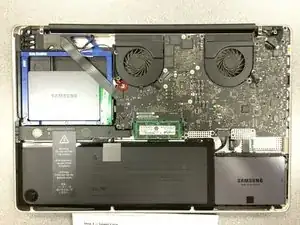

important to reassemble the "lower case" successfully: the threads of the seven 3mm phillips screws are drilled at an angle :-/
mysterioes -
Same issue with me. After reassembling my 13-inch and my 17-inch, one of the screws are sticking out ever so slightly. Very annoying, especially since I scratch whatever surface I'm on now.
Kyle Spadaro -
Very important note; this guide is NOT correct for the Macbook Pro 17" A1297 late '11.
The A1297 has an assembly adjacent to the optical drive, identifiable by 4 antenna connectors, 1 usb cable (with very small connector) and one PCI-e flat cable running across the optical drive.
I did not take pictures, but found one on the web. I'm very new to iFixit and have no idea yet on how to create a guide, but here's the picture showing the assembly on top (this pic only has 3 antenna wires, the A1297 has 4, but at least you'll know what to look for.
- carefully undo all connections and 2 screws
- remove the assembly and flip it over
- again carefully remove the shielding tape
- undo 3 tiny screws
- gently pry the airport card from the assembly (the flat cable will be a bit of a pain)
- reverse process with replacement card.
image can be found here:
https://dl.dropboxusercontent.com/u/2446...
Remon -
It helps if you mark the holes where the long screws go so you can easily find them when the time comes to button things up. Also, a little dish or custard cup to hold those tiny screws is essential.
Human -
3 x 13.5 mm screws are actually TWO different types! Return to EXACT SAME HOLES.
-I discovered this on my mid-2010, but from comments, sounds like it may affect other models as well
2 x 13.5 mm screws are pointed ends
1 x 13.5 mm screw is a FLAT end <- CORNER HOLE
These areTWO slightly different lengths, and must return to correct holes. If you put the flat end screw in the wrong hole, it will stick out slightly. If you put either of the pointed screws in the wrong hole, they will go in all the way, but will not catch threads, and will simply fall out when laptop is flipped back over.
scottbernardis -
I printed out the image above and taped each screw to the photo as I removed each one, just to make sure I put them in the right location.
Grace Morris -
This is a brilliant suggestion! I did this for all the steps that involved removing screws, numbered the sheets, and that made it very easy to put it all back together in reverse. Thanks!
Steve Adamczyk -
Be sure to use Loctite on the screws when re-attaching the bottom of the computer. The screws can and will fall out once they have been removed for repairs if you do not put Loctite on them when you reuse them. Otherwise, purchase new screws before repairing the computer as the new screws come with Loctite material on them. (I have personal experience with this problem.)
johnpartridge -
Be sure NOT to Buy this Battery from iFixit. I bought it from eustore.ifixit.com and the Condition of Battery is : Service Battery ,
from the &&^&^$^ first day.
Till today my battery Cycle Count is: 80.
I’ve tried everything as: Battery Calibration, resetting the SMC, PRAM, reinstalling the battery,
and Service Battery warning still there.
Just DO NOT BUY crappy, trash from here.
I have very bad experience.
Doruntin Koci -
Hi Doruntin,
we’re more than sorry to hear about your bad experience.
I’ll inform our customer service team who’ll reach out to you and offer either a replacement or reimbursement.
If ever you’d need assistance again, please feel free to directly write to eustore@ifixit.com, as comments are not regularly checked for service issues.
I’m confident that we’ll find the solution that suits you best!
Sandra Hiller -
PLEASE OBSERVE: The image of the left speaker used is NOT for a 2011 model. A 17inch MacBook Pro A1297 - LEFT SPEAKER + MICROPHONE - 2011 has IDENTIFYING NUMBER: Apple Part #:922-9821, 922-9822. And its COMPATIBILITY: 17 inch MacBook Pro Unibody A1297 - Early 2011 MC725LL/A 2.2 i7 - Early 2011 MC725LL/A 2.3 i7 - Late 2011 MD311LL/A 2.4 i7 - Late 2011 MD311LL/A 2.5 i7
kenneth krabat -