Introduction
Use this guide to replace your Bluetooth board.
Tools
Parts
-
-
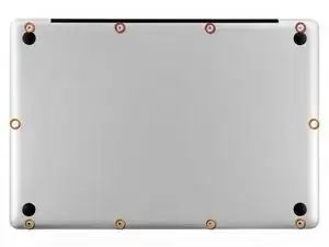
Remove the following ten screws securing the lower case to the upper case:
-
Three 13.5 mm Phillips screws.
-
Seven 3 mm Phillips screws.
-
-
-
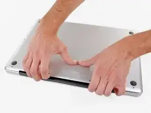
Wedge your fingers between the lower case and the vent, and lift upward to release the two clips holding the lower case to the upper case.
-
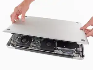
Remove the lower case.
-
-
-
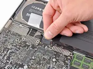
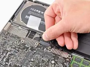
If present, grab the plastic tab attached to the battery connector and pull it toward the front edge of the device. For Late-2011 models the battery connector will not have a tab and is simply a plug that inserts straight down into the motherboard--to remove pry the plug straight up.
-
-
-
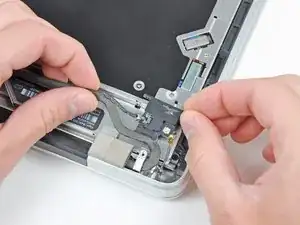
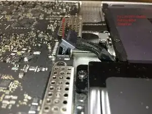
Carefully pull the Bluetooth cable toward the fans to disconnect it from the Bluetooth board.
-
-
-
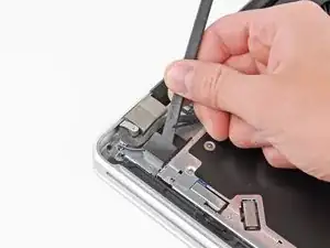
Use the flat end of a spudger to peel the thin plastic cover off the top and sides of the Bluetooth board housing.
-
-
-
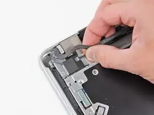
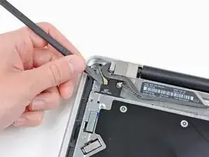
Use the flat end of a spudger to pry the Bluetooth antenna connector up and off its socket on the Bluetooth board.
-
-
-
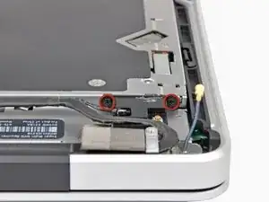
Remove the two 2.2 mm Phillips screws securing the Bluetooth housing to the side of the optical drive.
-
-
-
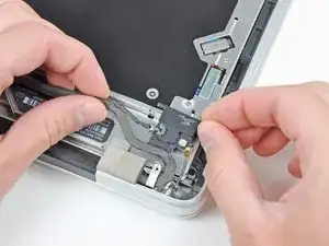
De-route the camera cable from its slot in the Bluetooth housing and remove the Bluetooth board from the upper case.
-
To reassemble your device, follow these instructions in reverse order.

important to reassemble the "lower case" successfully: the threads of the seven 3mm phillips screws are drilled at an angle :-/
mysterioes -
Same issue with me. After reassembling my 13-inch and my 17-inch, one of the screws are sticking out ever so slightly. Very annoying, especially since I scratch whatever surface I'm on now.
Kyle Spadaro -
Very important note; this guide is NOT correct for the Macbook Pro 17" A1297 late '11.
The A1297 has an assembly adjacent to the optical drive, identifiable by 4 antenna connectors, 1 usb cable (with very small connector) and one PCI-e flat cable running across the optical drive.
I did not take pictures, but found one on the web. I'm very new to iFixit and have no idea yet on how to create a guide, but here's the picture showing the assembly on top (this pic only has 3 antenna wires, the A1297 has 4, but at least you'll know what to look for.
- carefully undo all connections and 2 screws
- remove the assembly and flip it over
- again carefully remove the shielding tape
- undo 3 tiny screws
- gently pry the airport card from the assembly (the flat cable will be a bit of a pain)
- reverse process with replacement card.
image can be found here:
https://dl.dropboxusercontent.com/u/2446...
Remon -
It helps if you mark the holes where the long screws go so you can easily find them when the time comes to button things up. Also, a little dish or custard cup to hold those tiny screws is essential.
Human -
3 x 13.5 mm screws are actually TWO different types! Return to EXACT SAME HOLES.
-I discovered this on my mid-2010, but from comments, sounds like it may affect other models as well
2 x 13.5 mm screws are pointed ends
1 x 13.5 mm screw is a FLAT end <- CORNER HOLE
These areTWO slightly different lengths, and must return to correct holes. If you put the flat end screw in the wrong hole, it will stick out slightly. If you put either of the pointed screws in the wrong hole, they will go in all the way, but will not catch threads, and will simply fall out when laptop is flipped back over.
scottbernardis -
I printed out the image above and taped each screw to the photo as I removed each one, just to make sure I put them in the right location.
Grace Morris -
This is a brilliant suggestion! I did this for all the steps that involved removing screws, numbered the sheets, and that made it very easy to put it all back together in reverse. Thanks!
Steve Adamczyk -
Be sure to use Loctite on the screws when re-attaching the bottom of the computer. The screws can and will fall out once they have been removed for repairs if you do not put Loctite on them when you reuse them. Otherwise, purchase new screws before repairing the computer as the new screws come with Loctite material on them. (I have personal experience with this problem.)
johnpartridge -
Be sure NOT to Buy this Battery from iFixit. I bought it from eustore.ifixit.com and the Condition of Battery is : Service Battery ,
from the &&^&^$^ first day.
Till today my battery Cycle Count is: 80.
I’ve tried everything as: Battery Calibration, resetting the SMC, PRAM, reinstalling the battery,
and Service Battery warning still there.
Just DO NOT BUY crappy, trash from here.
I have very bad experience.
Doruntin Koci -
Hi Doruntin,
we’re more than sorry to hear about your bad experience.
I’ll inform our customer service team who’ll reach out to you and offer either a replacement or reimbursement.
If ever you’d need assistance again, please feel free to directly write to eustore@ifixit.com, as comments are not regularly checked for service issues.
I’m confident that we’ll find the solution that suits you best!
Sandra Hiller -
PLEASE OBSERVE: The image of the left speaker used is NOT for a 2011 model. A 17inch MacBook Pro A1297 - LEFT SPEAKER + MICROPHONE - 2011 has IDENTIFYING NUMBER: Apple Part #:922-9821, 922-9822. And its COMPATIBILITY: 17 inch MacBook Pro Unibody A1297 - Early 2011 MC725LL/A 2.2 i7 - Early 2011 MC725LL/A 2.3 i7 - Late 2011 MD311LL/A 2.4 i7 - Late 2011 MD311LL/A 2.5 i7
kenneth krabat -