Introduction
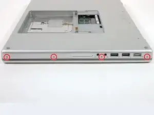
Provides power to the machine and includes all ports on the left side of the machine.
-
-
Use your fingers to push both battery release tabs away from the battery and lift the battery out of the computer.
-
-
-
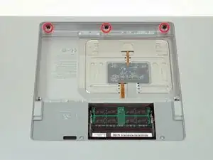
Remove the four identical Phillips 3.4 mm screws from the memory door. These screws have 4 mm diameter heads rather than the 3 mm heads on the body screws.
-
-
-
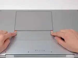
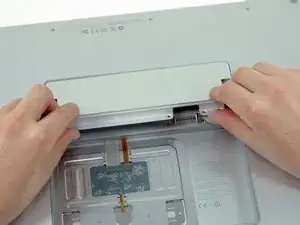
Lift the memory door up enough to get a grip on it, and slide it toward you, pulling it away from the casing.
-
-
-
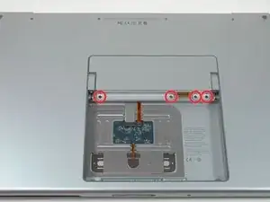
Remove the three Phillips screws in the battery compartment near the latch. Apple was nice enough to tilt these screws at a slight angle to make them easier to remove. On the A1261 these screws have 4 mm diameter heads rather than the 3 mm heads on the body screws.
-
-
-
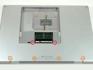
Remove the following six screws:
-
Two 14.5 mm T6 Torx screws on either side of the RAM slot.
-
Four 3.4 mm Phillips screws along the hinge.
-
-
-
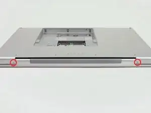
Rotate the computer 90 degrees and remove the two Phillips screws from the rear of the computer.
-
-
-
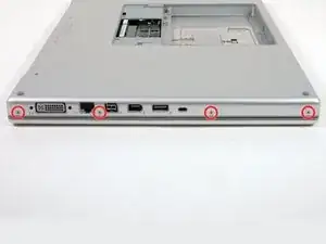
Rotate the computer 90 degrees again and remove the four Phillips screws from the side of the computer.
-
-
-
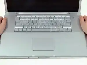
Lift up the back of the case and work your fingers along the sides, freeing the case as you go. Once you have freed the sides, you may need to rock the case up and down to free the front of the upper case.
-
-
-
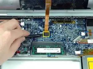
Disconnect the trackpad and keyboard ribbon cable from the logic board.
-
Remove the upper case.
-
-
-
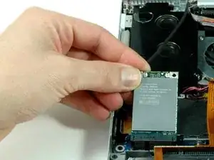
Remove the single black 4.3 mm T6 Torx screw from the top right corner of the AirPort Extreme card.
-
-
-
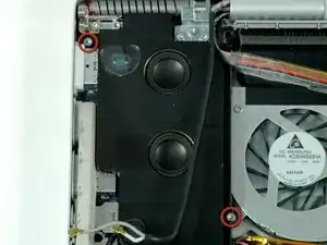
Remove the two silver T6 Torx screws from the top left 8 mm and bottom right 10 mm corners of the left speaker assembly.
-
-
-
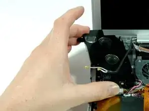
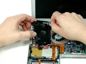
Lift up on the left speaker assembly and rotate it slightly. It is not possible to entirely remove the speaker yet, as it is still connected to the left I/O board beneath.
-
-
-
Disconnect the two cables securing the left speaker to the I/O board.
-
Lift the left speaker out of the upper case.
-
-
-
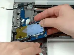
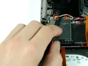
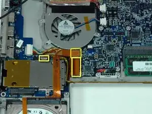
Disconnect the hard drive ribbon cable and the left I/O board ribbon cable from the logic board.
-
Disconnect the right speaker connector from the left I/O board.
-
-
-
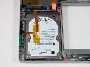
Remove the two silver T6 Torx screws securing the gray metal retaining bracket to the right side of the hard drive. 8 mm upper and 10 mm lower.
-
Lift the gray metal retaining bracket out of the computer.
-
-
-
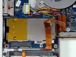
Remove the four 4.2 mm black or silver T6 Torx screws securing the left I/O board to the lower case.
-
Disconnect the large power connector from the left I/O board.
-
-
-
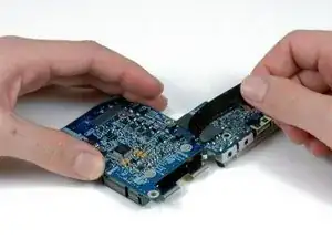
Move the orange hard drive ribbon out of the way with one hand. Use your other hand to lift up the right side of the left I/O board and slide it out of the computer.
-
-
-
Turn the left I/O board over.
-
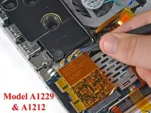
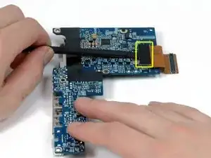
Use a spudger to disconnect the short orange cable from the left I/O board.
-
-
-
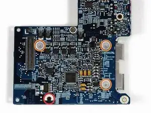
Peel up the L-shaped piece of black tape on the I/O board to reveal the two silver Phillips screws beneath.
-
-
-
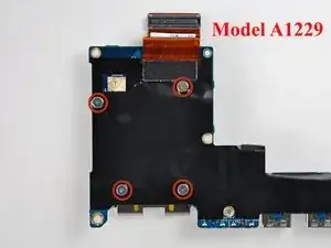
Remove the following four screws:
-
One 3.2 mm black Phillips screw with a small head.
-
Three 1.3 mm silver Phillips screws with large heads.
-
The I/O board is now free from the ExpressCard cage.
-


To reassemble your device, follow these instructions in reverse order.

2 comments
Great guide! Thanks!
Now to change the hinges and LCD screen! Already upgraded RAM (6GB), SSHD (1TB), and a new keyboard.
IT'S ALIIIIIVVVVEEEEE!!! LOL
Jason -
Are the A1229 Macbook I O Board Magsafe interchangeable with A1151 Macbook 17" ? Thanks
Before upgrading to a larger HD, you'll want to "clone" your original HD using the donation-ware program "Carbon Copy Cloner" (http://www.bombich.com/). Put the new HD in an external case; clone the original; test the clone (by starting up with it), then take apart the MacBook to put the new HD in the MacBook, and the original in the external case for use as a backup, etc. (You can't just drag the contents of the original HD to the new HD, and expect it to work; not since the days of OS 9 and before.)
amiller770 -