
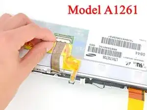
Introduction
Replacing the front display bezel requires removal of nearly every component in your display assembly.
-
-
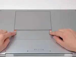
Use your fingers to push both battery release tabs away from the battery and lift the battery out of the computer.
-
-
-
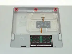
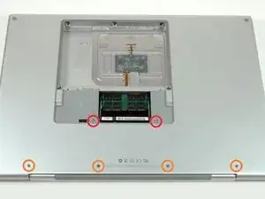
Remove the four identical Phillips 3.4 mm screws from the memory door. These screws have 4 mm diameter heads rather than the 3 mm heads on the body screws.
-
-
-
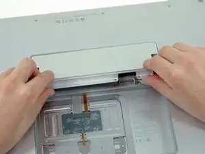
Lift the memory door up enough to get a grip on it, and slide it toward you, pulling it away from the casing.
-
-
-
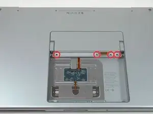
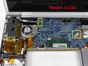
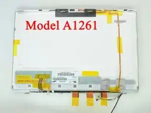
Remove the three Phillips screws in the battery compartment near the latch. Apple was nice enough to tilt these screws at a slight angle to make them easier to remove. On the A1261 these screws have 4 mm diameter heads rather than the 3 mm heads on the body screws.
-
-
-
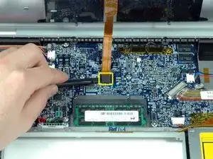
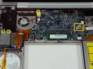
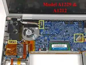
Remove the following six screws:
-
Two 14.5 mm T6 Torx screws on either side of the RAM slot.
-
Four 3.4 mm Phillips screws along the hinge.
-
-
-
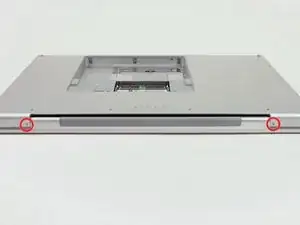
Rotate the computer 90 degrees and remove the two Phillips screws from the rear of the computer.
-
-
-
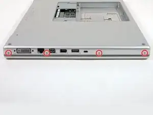
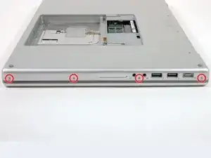
Rotate the computer 90 degrees again and remove the four Phillips screws from the side of the computer.
-
-
-
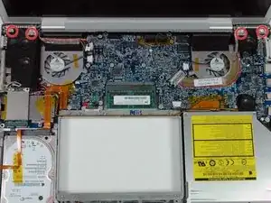
Lift up the back of the case and work your fingers along the sides, freeing the case as you go. Once you have freed the sides, you may need to rock the case up and down to free the front of the upper case.
-
-
-
Disconnect the trackpad and keyboard ribbon cable from the logic board.
-
Remove the upper case.
-
-
-
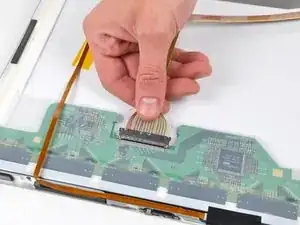
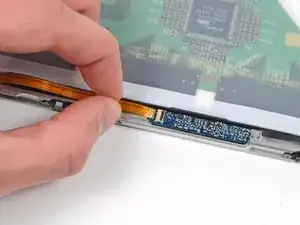
Disconnect the two antenna cables from the AirPort Extreme card, the iSight and inverter cables from the left side of the logic board, and the display data cable from the right side of the logic board. Be careful to slide the connectors as they may become damaged otherwise.
-
Carefully peel the iSight and inverter cables off the top of the left fan and de-route the AirPort antenna cables from the channel in the left speaker.
-
-
-
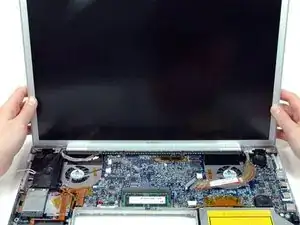
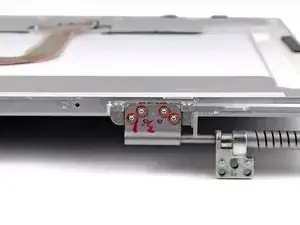
Remove the ten silver T6 Torx screws securing the display (five on each side-take note that the inside screws on both sides are longer with a thinner head).
-
-
-
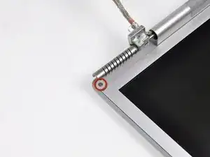
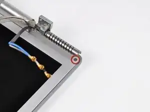
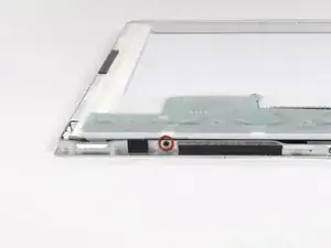
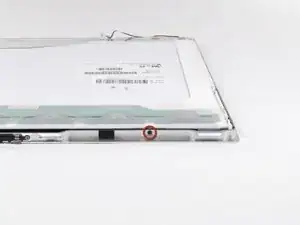
Remove the Phillips screws from the lower left and right corners of the display (two screws total).
-
-
-
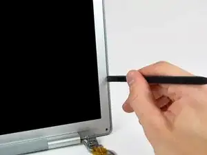
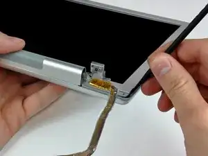
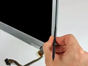
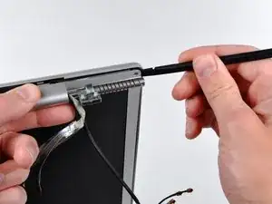
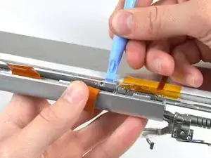
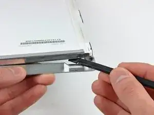
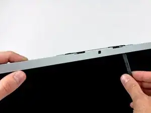
Insert the flat end of a spudger perpendicular to the face of the display between the plastic strip attached to the rear bezel and the front bezel.
-
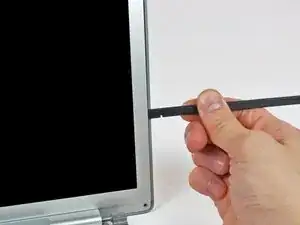
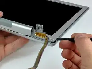
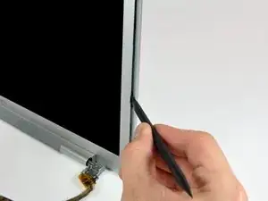
With the spudger still inserted, rotate it away from the display to separate the front and rear bezels.
-
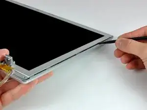
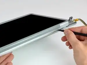
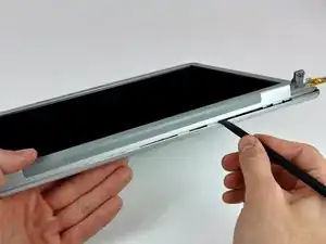
Work along the right edge of the display until the rear bezel is evenly separated from the front bezel.
-
-
-
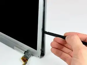
Insert your spudger between the front and rear display bezels at the lower right corner of the display.
-
Pry the rear bezel away from the front bezel to slightly separate the bottom edge of the rear display bezel.
-
-
-
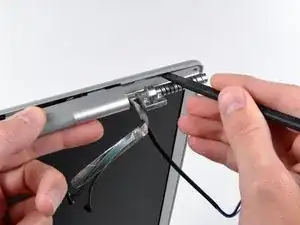
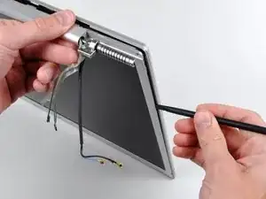
Insert the flat end of a spudger into the gap between the rear display bezel and the clutch cover.
-
Twist the spudger to separate the lower edge of the rear display bezel from the clutch cover.
-
Work along the lower edge of the rear bezel until it is evenly separated from the clutch cover.
-
-
-
Now that the right and bottom edges of the rear bezel are slightly separated from the front bezel, use a spudger to pop the rear bezel off the tabs near the lower right corner of the display.
-
-
-
Insert the flat end of a spudger between the front bezel and the plastic strip attached to the rear bezel near the screw holes at the bottom corners of the display.
-
Rotate your spudger toward the rear bezel to separate it from the front bezel.
-
-
-
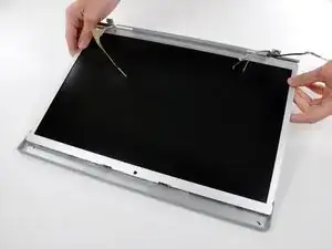
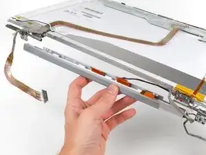
Slightly lift the lower edge of the display and pull it away from the rear display bezel.
-
The rear display bezel remains.
-
-
-
Disconnect the inverter cable by pulling its connector away from the socket on the inverter board.
-
-
-
Disconnect the backlight connector from the inverter board.
-
Remove the inverter from the display.
-
-
-
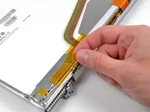
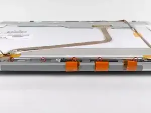
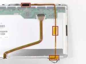
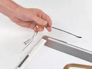
Use the flat end of a spudger to carefully peel off the three antenna straps stuck to the lower edge of the LCD.
-
-
-
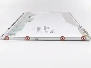
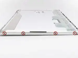
Remove the five Phillips screws securing the clutch cover to the bottom edge of the front display bezel.
-
-
-
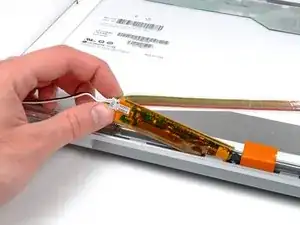
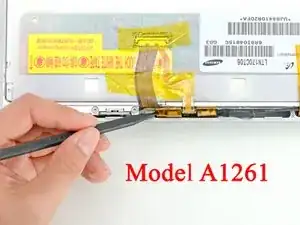
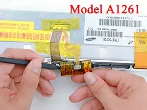
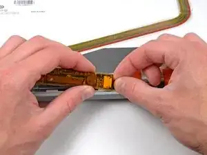
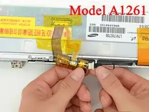
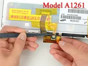
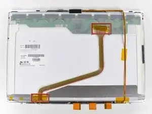
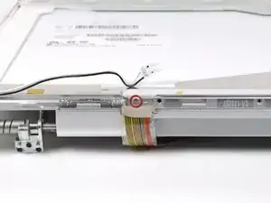
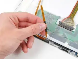
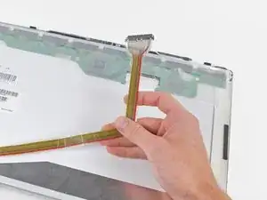
Disconnect the display data cable from the LCD by pulling it toward the bottom edge of the display.
-
-
-
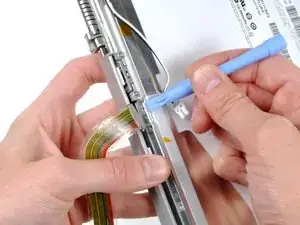
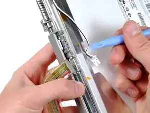
While pulling the clutch assembly away from the clutch hinge with one hand, insert an iPod opening tool between the clutch cover and the front display bezel to lift the clutch cover over the retaining pin on the front display bezel.
-
Pull the clutch assembly away from the front display bezel.
-
-
-
Repeat the process covered in the previous step to free the other side of the clutch assembly from the front display bezel.
-
-
-
Remove the clutch assembly from the front display bezel, minding any cables that may get caught.
-
-
-
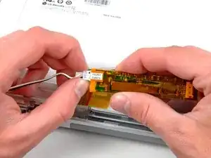
Use the tip of a spudger or your fingernail to flip up the ZIF retaining flap on the camera cable socket at the edge of the camera board near the top center of the front display bezel.
-
Pull the camera cable out of its socket.
-
-
-
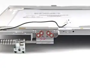
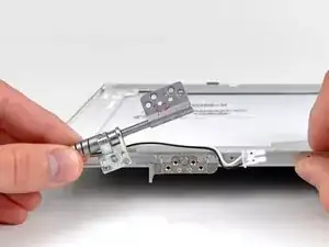
Remove the four 3.5 mm T6 Torx screws securing the left clutch hinge to the front display bezel.
-
Remove the left clutch hinge from the front display bezel.
-
-
-
Remove the four 3.5 mm T6 Torx screws securing the right clutch hinge to the front display bezel.
-
Remove the right clutch hinge from the front display bezel.
-
-
-
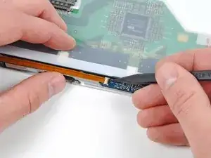
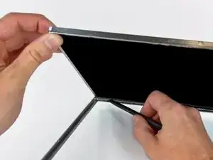
Use the flat end of a spudger to gently lift one of the top corners of the LCD out of the front bezel.
-
-
-
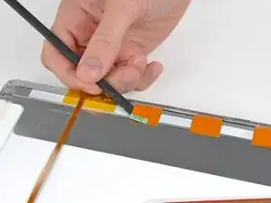
Work your way along the top edge of the LCD, slowly prying the attached steel strip away from the front bezel.
-
Continue prying the LCD off the front bezel along the left side of the display.
-
-
-
Now that the top and left edges are free, slightly lift the LCD out of the front bezel for enough room to pry the steel strip along the lower edge of the LCD away from the front bezel.
-
Pry along the lower edge of the LCD until it is freed from the adhesive on the front bezel.
-
-
-
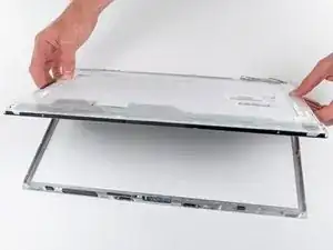
Lift the LCD out of the front bezel, minding any cables that may get caught.
-
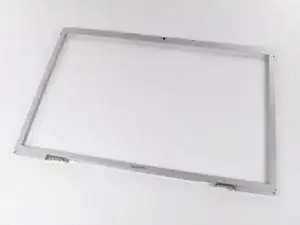
Front bezel remains.
-

To reassemble your device, follow these instructions in reverse order.

5 comments
Are the bezels on the A1151 A1212 A1229 and A1261 all interchangeable? (can the front bezel from any of those models go on my a1229?)
They are very similar but a search on the internet shows three different part numbers.
Seriously consider using a screw sorter when doing this guide. I actually use a fishing tackle organizer. They have lids you can close, thus preventing any accidental screw spillage. I actually use two sorters, one for the case screws, and one for whatever parts inside I am repairing.
Thanks, my MacBook Pro is now getting full use once more. This guide was very helpful. It was a smooth process.
Before upgrading to a larger HD, you'll want to "clone" your original HD using the donation-ware program "Carbon Copy Cloner" (http://www.bombich.com/). Put the new HD in an external case; clone the original; test the clone (by starting up with it), then take apart the MacBook to put the new HD in the MacBook, and the original in the external case for use as a backup, etc. (You can't just drag the contents of the original HD to the new HD, and expect it to work; not since the days of OS 9 and before.)
amiller770 -