Introduction
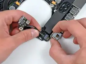
Replacing the MagSafe DC-In board requires removal of the logic board.
-
-
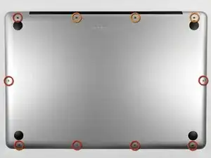
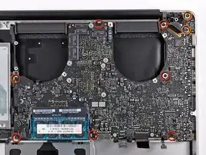
Remove the following ten screws securing the lower case to the upper case:
-
Three 13.5 mm (14.1 mm) Phillips screws.
-
Seven 3 mm Phillips screws.
-
-
-
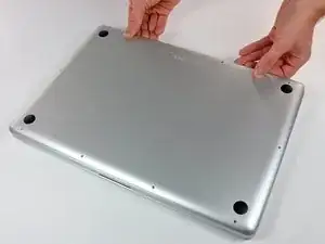
Using both hands, lift the lower case near the vent to pop it off two clips securing it to the upper case.
-
Remove the lower case and set it aside.
-
-
-
Remove the two 7.4 mm Tri-point screws securing the battery to the upper case.
-
Note: For certain repairs (e.g. hard drive), removing the battery is not necessary but it prevents any accidental shorting of electronics on the motherboard. If you do not remove the battery, please be careful as parts of the motherboard might be electrified.
-
-
-
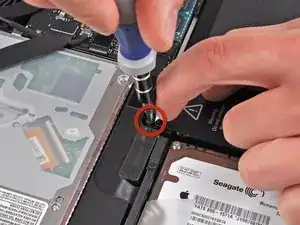
Use the tip of your finger to carefully peel back the corner of the warning label to reveal a hidden Tri-point screw.
-
Remove the last 7.4 mm Tri-point screw securing the battery to the upper case.
-
-
-
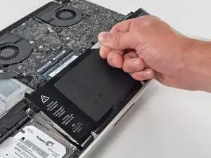
Lift the battery by its plastic pull tab and slide it away from the long edge of the upper case.
-
-
-
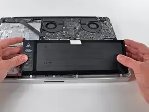
Tilt the battery away from the logic board enough to access the battery cable connector.
-
Pull the battery cable connector away from its socket on the logic board and remove the battery from the upper case.
-
Charge it to 100%, and then keep charging it for at least 2 more hours. Next, unplug and use it normally to drain the battery. When you see the low battery warning, save your work, and keep your laptop on until it goes to sleep due to low battery. Wait at least 5 hours, then charge your laptop uninterrupted to 100%.
-
If you notice any unusual behavior or problems after installing your new battery, you may need to reset your MacBook's SMC.
-
-
-
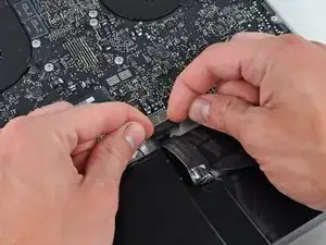
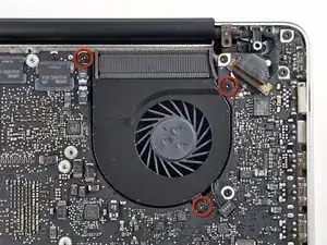
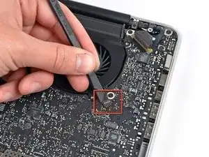
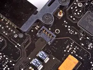
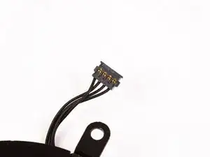
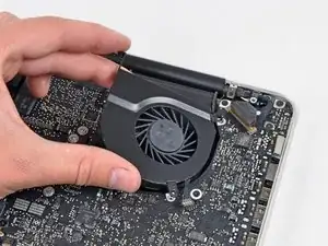
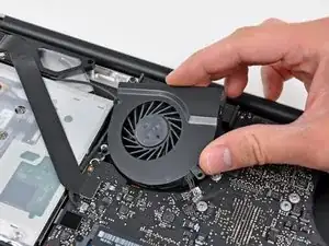
Use the flat end of a spudger to pry the right fan connector up out of its socket on the logic board.
-
Remove the right fan from the upper case.
-
-
-
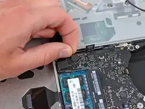
Use the flat end of a spudger to pry the AirPort / Bluetooth ribbon cable up off its socket on the logic board.
-
-
-
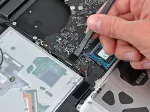
Use the flat end of a spudger to pry the optical drive cable connector up from the logic board.
-
-
-
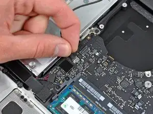
Carefully pull the subwoofer/right speaker cable up to lift its connector out of its socket on the logic board.
-
-
-
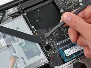
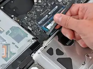
Use the flat end of a spudger to pry the hard drive cable connector up out of its socket on the logic board.
-
-
-
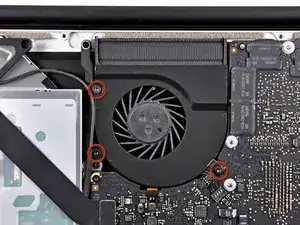
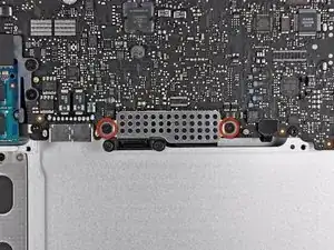
Remove the two short Phillips screws securing the small EMI shield to the logic board.
-
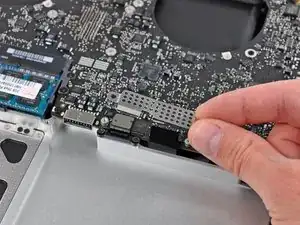
Remove the EMI shield from the logic board.
-
-
-
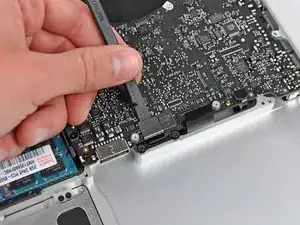
Use the flat end of a spudger to pry the trackpad cable connector up out of its socket on the logic board.
-
-
-
Use your fingernail to carefully flip up the keyboard ribbon cable retaining flap.
-
Use the tip of a spudger to pull the keyboard ribbon cable straight out of its socket.
-
-
-
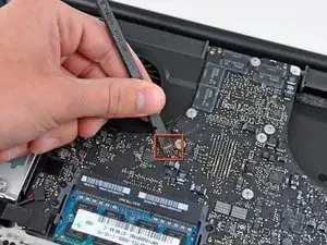
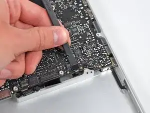
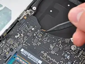
Use the flat end of a spudger to pry the battery indicator cable connector up out of its socket on the logic board.
-
-
-
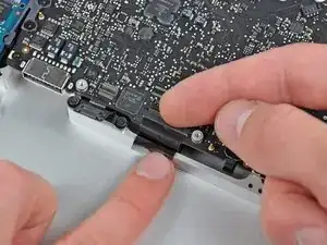
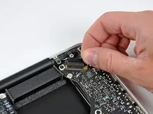
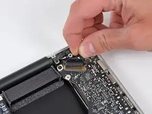
Grab the plastic pull tab secured to the display data cable lock and rotate it toward the DC-In side of the computer.
-
Pull the display data cable straight out of its socket.
-
-
-
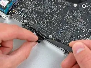
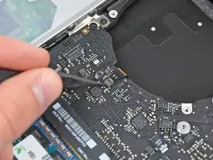
Use the tip of a spudger or your fingernail to flip up the retaining flap on the keyboard backlight ribbon cable socket.
-
Pull the keyboard ribbon cable straight out of its socket.
-
-
-
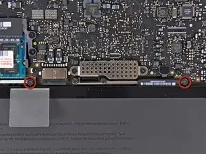
Remove the following screws:
-
Seven 3.3 mm T6 Torx screws securing the logic board to the upper case.
-
Two 8 mm T6 Torx screws securing the DC-In board to the upper case.
-
-
-
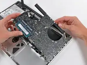
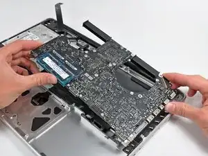
Carefully lift the logic board assembly from the left side and work it out of the upper case, minding the port side that may get caught during removal.
-
-
-
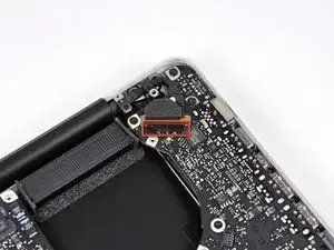
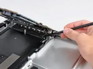
Lift the logic board enough to gain clearance and use a spudger to pry the microphone up off the upper case.
-
-
-
Slide the logic board away from the port openings and lift the assembly out of the upper case.
-
To reassemble your device, follow these instructions in reverse order.

4 comments
Excellent walkthrough! This was my first ifixit repair and I was able to successfully replace my damaged magsafe board. The 64-Bit driver kit was the perfect companion to this project and the many more that will come in the future.
Thanks for your help! I think something on the mainboard is toast and the computer is a total loss, but it was worth it to take a chance and see if the cheap mag board would fix it. Good guide!
Good guide - gave me the confidence to have a go - thanks - I would say to others be very gentle with the cable connectors - mine weren’t exactly the same type as shown in the guide - be patient and you’ll work it out.
Step 1 (technically step 9 - replacing the base plate) Apparently one of my screws was a micron or two smaller than the others. This screw belongs to the hole above the optical drive, which is also apparently a couple of microns smaller than the others. It took seven attempts to figure which screw had originally been in that hole; all the other screws were too large, but fitted perfectly everywhere else.
Bizarre much?
Will -
It might be a matter of how the screws are driven in, and not that they're slightly different sizes. When I reassembled my MacBook, a couple of the screws, including the one over the optical drive you mention, were hard to drive in and jutted up a little bit instead of sitting entirely flush. Swapping screws didn't help. The solution was to unscrew them and drive them in at a bit of an angle - perpendicular to the slightly curved surface of the back plate where the screw holes were, instead of fully vertical with respect to the ground the Macbook is sitting on. Doing it that way, the screws were easier to drive in and they all ended up flush in their holes. Didn't matter which screws they were. (I swapped a few around just to check after reading this.)
Andrew Janke -
I had no such screw issues. Either there are differences in manufacturing lots or I just got incredibly lucky during reassembly!
xtophr -