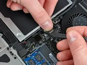
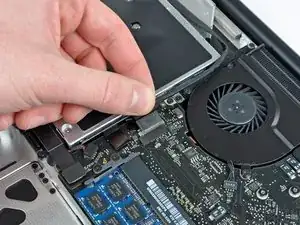
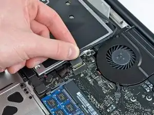
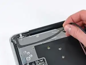
Introduction

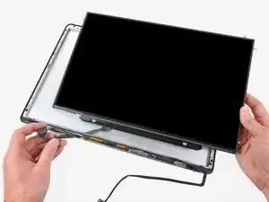
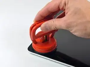
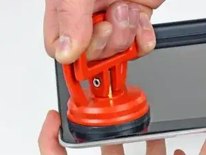
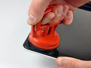
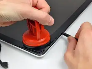
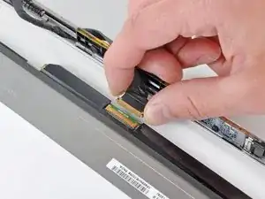
Save money by replacing just the LCD rather than the whole display assembly. This guide is not applicable for anti-glare displays.

  1. 2ycdtRrTgDZgPtCG
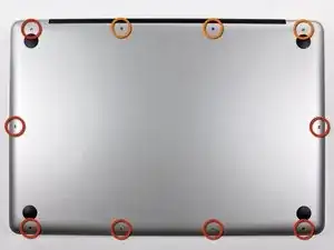
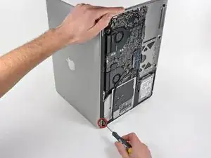
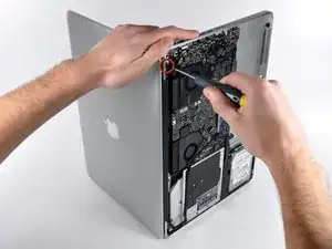
    • Remove the following ten screws securing the lower case to the upper case:

    • Seven 3 mm Phillips screws.

    • Three 13.5 mm Phillips screws.

    May be helpful to have more distinct colors to identify the different screws.

    Victor Caamano -

  2. wyETETuUDDGNPgIh
    wyETETuUDDGNPgIh
    vLOGRGZI2eygR2sJ
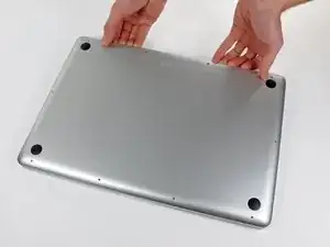
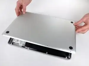
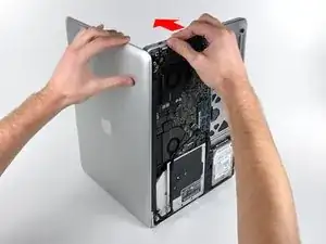
    • Using both hands, lift the lower case near the vent to pop it off two clips securing it to the upper case.

    • Remove the lower case and set it aside.

  3. fBWga2JEZT2tmqRt
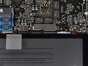
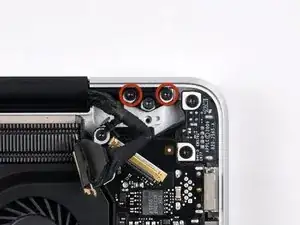
    • Remove the two 5-Point Pentalobe screws along the top edge of the battery.

    • You do not necessarily have to follow steps 3-6 to remove the battery in order to replace the hard drive. However it is recommended to remove all power sources from electronics before working on them.

    Question: why do you remove the battery? According to Apple's official manual, this is not required (not for the mid-2009 and not for the mid-2010 15-inch MacBook Pro) - see pages 37 ff:

    http://manuals.info.apple.com/en_US/MacB...

    http://manuals.info.apple.com/en_US/MacB...

    alexkli -

    Quote from alexkli:

    Question: why do you remove the battery? According to Apple's official manual, this is not required (not for the mid-2009 and not for the mid-2010 15-inch MacBook Pro) - see pages 37 ff:

    http://manuals.info.apple.com/en_US/MacB...

    http://manuals.info.apple.com/en_US/MacB...

    I'm interested by your experience.

    Did you have removed the optical drive without removing the battery ?

    I'm just in this step now and if it is possible I would proceed like you because removing the battery void the warranty (and there is a sticker).

    Thanks in advance.

    youyou -

    Looks like my note to step 3 appears on all repair guides that have the same step. I meant that in the context of the hard drive replacement only.

    Did you have removed the optical drive without removing the battery ?

    I haven't yet done anything, waiting for my MacBook Pro 15 inch mid-2010 to arrive.

    alexkli -

    I missed the notes and went ahead and purchased the 5 point driver for the battery before I realized it was not necessary.

    I've edited the repair guide to remove the section on the battery, but I don't have the points to approve the changes.

    Chris Davis -

    Please note - the step about removing the battery is part of a pre-requisite guide, that is used for many of the guides, most that do require removal of the battery. Also, working inside a disassembled laptop with the battery still connected risks damaging/shorting out very expensive parts.

    Eric Essen -

    Absolutely. To be clear -- ALL of the above discussion is ONLY in reference to replacing the hard drive.

    Chris Davis -

    I replaced a hard drive in a MacBook Pro of an earlier model than this without removing the battery. The hard drive wasn't right. It only worked at about half speed, and I had to replace it once more. The second time I removed the battery and all went well. The recommendation by the iFixit staff to remove the battery before working on electronic equipment is a good one.

    doug -

    What is the size of those screws... I have rounded off the socket on mine and would like to replace them.

    Ghatothkach Yadav -

    I measured the screw size, using a micrometer, its about 1.523mm in diameter and 3.186mm in length. Not sure what screw size that is. They are not easily available I guess, unless someone is selling used ones on ebay

    Ghatothkach Yadav -

  4. 51GhiHAUMgp3IL1V
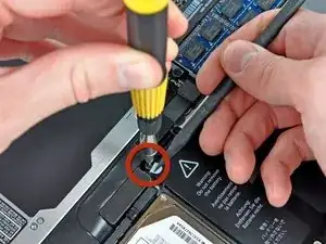
    • Use the tip of a spudger to bend back the finger of the "Warning: Do not remove the battery" sticker while you remove third five-point Pentalobe screw hidden underneath.

  5. DxGirDoRhQVXvY1S
    DxGirDoRhQVXvY1S
    iCPMLfZ6gsvCV1Gm
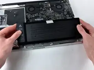
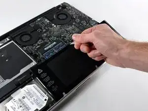
    • Lift the battery by its plastic pull tab and slide it away from the long edge of the upper case.

    • Do not try to completely remove the battery just yet.

    Removing the battery is not necessary for the hard drive removal/replacement procedures.

    Erik -

    My T6 (appears to be same screw driver you have - $6 on amazon for 20piece set) did NOT fit int he battery screws...not sure if I had the wrong screws or what, but I went ahead w/o battery steps and it was pretty easy.

    Anthony Ettinger -

    I also noticed that the new SDD (from crucial) didn't have the 4 screws, so I had to move those off the old HD and onto the new one.

    Anthony Ettinger -

    Just had the same issue: T6 does not fit the battery screws ;-( ... but with a little bit more preassure it was possible to remove the screws.

    dirkvloenwagner -

  6. XfHIrygDNgEDWQtJ
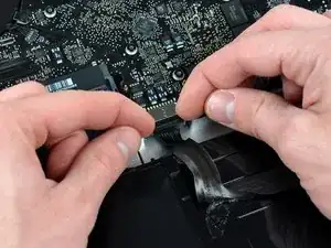
    • Tilt the battery back enough to access the battery cable connector.

    • Pull the battery cable connector away from its socket on the logic board and remove the battery from the upper case.

    • If you're installing a new battery, you should calibrate it after installation.

    Excellent guide

    Kola Ajibade -

  7. e6ACMjR4RwNbvOU2
    • Apple sticks a small strip of clear plastic with adhesive applied to one side of the logic board behind the camera cable connector to keep it in its socket. When moving it out of the way, be sure not to break any surface-mount components off the logic board.

    • Use the tip of a spudger to rotate the plastic retainer away from the camera cable connector.

  8. egu2ZAPLAxrSAklX
    egu2ZAPLAxrSAklX
    Hih3LXym2gKoPOKB
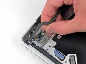
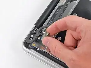
    • Pull the camera cable away from its socket on the logic board.

    • Pull the connector parallel to the face of the logic board, not straight up.

  9. MMq6rZB44lRK3qme
    • Peel the camera cable off the adhesive securing it to the body of the optical drive.

  10. tUYelyy4dFWd2PgR
    tUYelyy4dFWd2PgR
    6Pxqo6QXisUH3BLG
    • This step is only required if you have an anti-glare display. If you have a glossy display, skip to step 12.

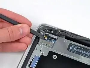
    • Disconnect the Bluetooth cable by pulling the male end straight away from its socket.

    • Pull the connector parallel to the face of the logic board, not straight up.

    • Use the flat end of a spudger to pry the Bluetooth antenna cable up from its socket on the board.

  11. 4fgVR6B1BkdXcIV1
    4fgVR6B1BkdXcIV1
    gMhPMSLu3GUwog6V
    • This step is only required if you have an anti-glare display.

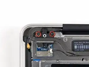
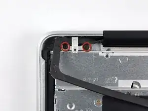
    • Remove the two 8 mm Phillips screws securing the Bluetooth/camera cable retainer to the upper case.

    • One of the screws may remain captive in the Bluetooth/camera cable ground loop. If replacing the display, be sure to transfer this screw to the new unit.

    • Lift the Bluetooth board/cable retainer assembly out of the upper case.

  12. OMInEMkJcFJmi1Ue
    OMInEMkJcFJmi1Ue
    TAhl3uIf5FPGwfRG
    • This step is only for glossy display machines. If you have an anti-glare display, skip this step.

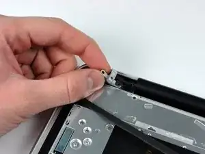
    • Remove the two 8 mm Phillips screws securing the camera cable retainer to the upper case.

    • One of the screws may remain captive in the camera cable ground loop. If replacing the display, be sure to transfer this screw to the new unit.

    • Lift the camera cable retainer out of the upper case.

  13. jagEtZZLMqTrSTxC
    jagEtZZLMqTrSTxC
    qUJE1PcUsitmgSEK
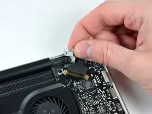
    • Grab the plastic pull tab secured to the display data cable lock and rotate it toward the DC-In side of the computer.

  14. rlRaHhJone5TIxnj
    rlRaHhJone5TIxnj
    hU1WhmGLVyJYV5FZ
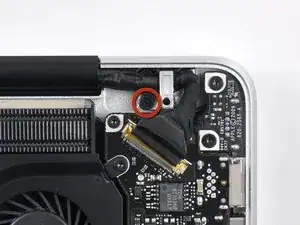
    • Remove the single 7 mm Phillips screw securing the display data cable retainer to the upper case.

    • This screw may remain captive in the display data cable ground loop. If replacing the display, be sure to transfer this screw to the new unit.

    • Remove the display data cable retainer from the upper case.

  15. QRSpZlYcPYBbCrvD
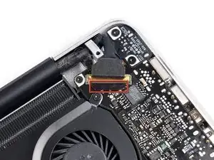
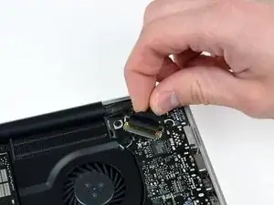
    • Be sure the display data cable lock is rotated toward the DC-In board before proceeding.

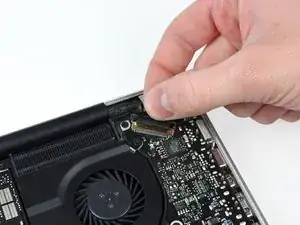
    • Pull the display data cable connector straight away from its socket.

    • Make sure to pull the connector parallel to the face of the logic board, not straight up from its socket.

  16. BJqRy2UvRXewsnMl
    BJqRy2UvRXewsnMl
    SGOq2aOaaoVSI3hv
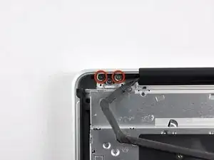
    • Remove the outer two T6 Torx screws securing both display hinges to the upper case (four screws total).

  17. 4IEufBYVCKFa5THl
    • Open your MacBook Pro so the display is perpendicular to the upper case.

    • Place your opened MacBook Pro on a table as pictured.

    • While holding the display and upper case together with your left hand, remove the remaining T6 Torx screw from the lower display bracket.

  18. aZVA2GxaNBWCgDFa
    • Be sure to hold the display and upper case together with your left hand. Failure to do so may cause the freed display/upper case to fall, potentially damaging each component.

    • Remove the last remaining T6 Torx screw securing the display to the upper case.

  19. SwsWvRDemQNlHrtC
    SwsWvRDemQNlHrtC
    Qjr35mVTnAbYiVXI
    IN3HUVrULpTNAVNM
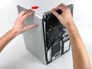
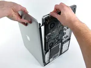
    • Grab the upper case with your right hand and rotate it slightly toward the top of the display so the upper display bracket clears the edge of the upper case.

    • Rotate the display slightly away from the upper case.

    • Lift the display up and away from the upper case, minding any brackets or cables that may get caught.

  20. ZUHkrFANKCRoSIBF
    ZUHkrFANKCRoSIBF
    ZcAloHY1OYVkkSnD
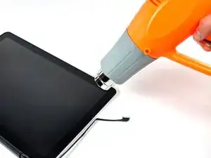
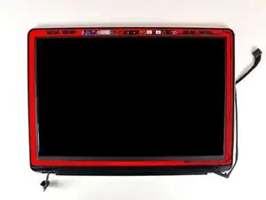
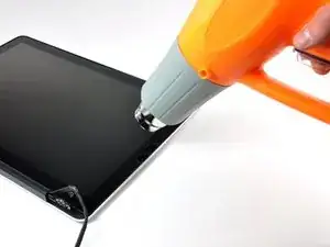
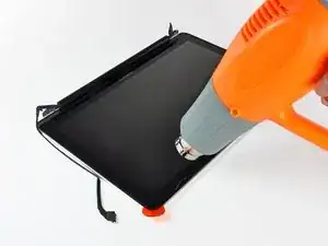
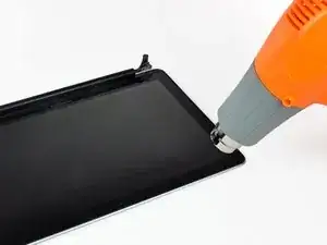
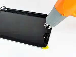
    • In the following steps, you will use a heat gun to soften the adhesive securing the outer black border around the underside of the front glass panel to the display. The area the adhesive is applied to is shown in red in the second picture.

    • Before starting, be sure to clean the display glass with lint-free cloth moistened with a mild solution; it will make the suction cup adhere better, and will make checking for dust on reassembly easier

    • With the heat gun set to low, start by heating the outer black border near the upper right corner of the glass panel.

    • Always aim the heat gun away from the soft rubber strip around the display glass. Heating the rubber will cause it to melt slightly, turning its finish from matte to glossy. Touching overheated rubber can cause it to permanently deform.

    • Due to the heat applied, it is normal for a layer of condensation to develop on the inside of the glass panel and/or the outside of the LCD. It can be removed with glass cleaner once the glass is separated from the display.

    Another caution is needed - the heat gun is capable of discoloring the LCD panel (giving uneven coloration) if it overheats. This is possible on the low setting. Proceed cautiously, heating in increments until the glass releases.

    Alden Stradling -

    I was wondering the same, is absolutely necessary to disassemble the screen to change the glass? Can I jump to step 21?

    caholzmann -

    To change just the glass I used a hair dryer it gives off enough heat to do the job. Stand the computer up on its cover with the key board standing up.start at a corner heat the adhesive as you go along. I Put credit cards in as I went along so the adhesive doesn't stick again. take your time . Its easy.

    Robert Lachman -

  21. UDRobaRBfJZHQUIF
    UDRobaRBfJZHQUIF
    py4SFtHRvbf2UZy2
    OmdWwfXYOuwXjjjI
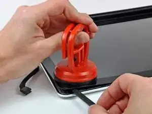
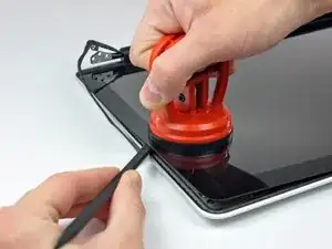
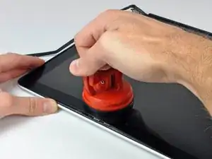
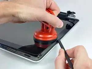
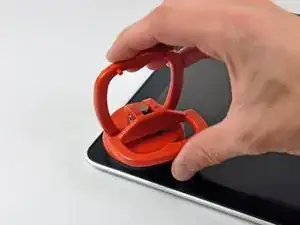
    • With the panel sufficiently heated, fasten a heavy-duty suction cup near the upper right corner of the display glass.

    • Don't fasten the suction cup on top of the rubber strip around the edge of the display glass.

    • To attach the suction cups we sell, first position the suction cup with the movable handle parallel to the face of the glass panel. While lightly holding the suction cup against the glass, raise the movable handle until it is parallel with the other handle.

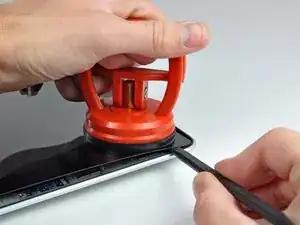
    • Slowly and gently pull the corner of the display glass up off the display assembly.

    • If only the top edge of the glass lifts up (as seen in the third picture), repeat steps one and two until you can lift up the corner of the panel.

    Sufficiently heated is a meaningless phrase here. Is it two minutes? Three? Fifteen? An hour? I have tried doing this for increasing amounts of time while avoiding doing damage to the machine, and nothing is working. Sufficient heating needs definition.

    Keith McComb -

    Hi Keith, the key here is that you want to warm the adhesive that's spread thoroughly behind the masked-black area of the glass around the screen to release, but not put enough heat at the rubber gasket that seals the closed top lid to the base. Too much heat, too soon, will deform the rubber. Too much and you'll never get the glass to release. The 2x that I have done this, however, even with sufficient (and significant) heat, I remember the glass taking a surprising amount of leverage to pull clear. A tactic: using your heat gun warm all the sides of the display from the front, in a circulating/racetrack fashion - about 20 rpm. After 30sec, focus on the left and top sides, seesawing from bottom left, to top left, to top right, and back. Do that at the same pace, about 5-10 passes. Then spend about 10 sec waving over the whole top left corner. That should get enough heat to enough places to help the glass separate to start placing picks, and you can continue to heat the margins as you progress.

    johnkimmel -

  22. W1lDnu6V55EFLhxy
    W1lDnu6V55EFLhxy
    sycwwpTOFyYMhAaR
    fOPEjlLX2jGIp5Kc
    • Gently lift the corner of the display glass enough to insert a spudger between it and the display assembly.

    • Use the flat end of a spudger to gently pry up the adhesive securing the front glass to the display.

    • Pry up the glass panel a few inches away from the upper right corner along the top and right edges of the display.

    Be careful with the spudger and the soft rubber strip around the glass. Since the rubber strip has been heated up by the heat gun, it is easily smushed and deformed by the spudger.

    Rob -

    Be patient and work slowly or else you will crack the glass like me.

    BillyRachel1 -

    I can not get the glass to come up despite two tries and dicsoloring the LCD with too much heat. Why can't I get the glass to budge at all?

    bollucks66 -

    It is better , instead of using the suction cup , to use small flat end spudger . The suction cup should be used first to detach the window from the gasket , not furthermore as it may brake the glass.

    Thierry de Montblanc -

    I didn’t have large suction cups and the small ones didn’t work for me. Instead, I used an opening tool to pry up the glass slightly and got a guitar pick under it. Then I slowly worked the pick around the top three sides of the glass, heating sections of glue as I went.

    Daniel Arnfield -

    I’ve managed to do it using hair dryer on max. First corner was though and took a lot of time to lift it. I decided to heat not only a corner but whole length and then it came off. I’ve put so much heat that was afraid I’ve damaged LCD, but it works fine. As BillyRachel1 said: patience is the way. In order to assemble it back I used old glue heated again. It’s easy but takes time.

    Note: Don’t do this at home if you have cats otherwise you going to spend next hour or so trying to remove their fur from between glass and LCD. It’s because they all levitate after using hot air and just wait to stick to the screen again.

    To be honest hardest thing was replacing clutch cover, took me so much time and I eventually cracked it.

    D. K. Labudek -

  23. WYhocb5QTXJeqHvT
    WYhocb5QTXJeqHvT
    IbE3VqTwXDvbPaAa
    • Use a heat gun to soften the adhesive under the black strip along the right side of the front glass panel.

    • Attach a suction cup along the right side of the front glass panel.

    • Pull up on the glass panel while you use the flat end of a spudger to separate it from the rest of the display assembly.

    • Continue working along the right edge of the front display glass until it is separated from the display.

    • It may be helpful to use a guitar pick or another thin plastic object to keep the upper right corner of the front glass panel from sticking back down to the display assembly.

    If you don't have a guitar pick, playing cards works too.

    Rob -

    I used old credit cards

    Robert Lachman -

  24. JJdSUU3FC4VWobTm
    JJdSUU3FC4VWobTm
    FHZ315NScC5MK1Jc
    • Use your heat gun to soften the adhesive under the black strip along the top edge of the glass display panel.

    • Attach a suction cup near the top edge of the glass display panel and use it to pull the glass panel up off the display.

    • Work along the top edge of the glass panel, carefully using the flat end of a spudger to separate the adhesive if necessary.

  25. xWA6KbUC1NOX2YsS
    xWA6KbUC1NOX2YsS
    BCjBlRVBEWAePEdc
    • Use a heat gun to soften the adhesive under the black strip near the upper left corner of the glass display panel.

    • Attach a suction cup near the upper left corner of the glass display panel.

    • Pull up on the suction cup and use the flat end of a spudger to carefully pry the glass display panel out of the display assembly.

    • Once the upper left corner has been separated from the display, it may be helpful to use a guitar pick or another thin plastic object to keep the glass from sticking back down to the display assembly.

  26. dO5W2cFAaUWJBHEX
    dO5W2cFAaUWJBHEX
    jgALlBdKLdPPAFAq
    • Use a heat gun to soften the adhesive under the black strip along the left side of the front glass panel.

    • Attach a suction cup along the left side of the front glass panel.

    • Pull up on the glass panel while you use the flat end of a spudger to separate it from the rest of the display assembly.

    • Continue working along the left edge of the front display glass until it is separated from the display.

  27. xZGqtW3MLOnYetlI
    xZGqtW3MLOnYetlI
    ReIWnURorEMfCKdb
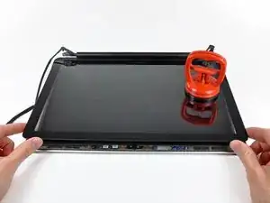
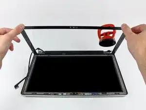
    • Now that the top, left, and right edges of the glass are free from the display, slowly lift the top edge of the glass panel and gently rotate it out of the display.

    • If necessary, use the flat end of a spudger to free the bottom edge of the glass display panel from the display assembly.

    • Before reassembling, be sure to clean both the inside of the glass display panel and the LCD as any dust or fingerprints trapped inside will be annoyingly visible when the machine is on.

    If you will be reusing the glass, with new adhesive, then you will want to remove the old adhesive. This is a bit of a pain, as alcohol doesn't work, and you need to be careful to avoid damaging the black screen border, which is black paint on the back (adhesive) side of the glass.

    To remove the adhesive, note that it is actually a thin film with rubber cement on both sides. First, use a razor to carefully pull up one corner of the film and gently peel it off of the glass. If you are gentle and slow, the underlying adhesive may also come off; if not, then rubbing with your finger or a hard rubber eraser will do the trick.

    griscom -

    what to do when new glass starts to peel after a week ?

    labig -

    If this is a rubber cement based glue, then would rubber solvent / thinner like N-Heptane help the removal process without damaging the black paint ?

    Sandman619 -

    Don’t remove glue. Just reuse it by heating and sticking it again.

    D. K. Labudek -

  28. cYIS2jRBXoYmJHcd
    cYIS2jRBXoYmJHcd
    UwQ5fvSIj6mpI3uM
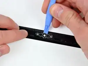
    • Insert the edge of a plastic opening tool between the display glass and the camera bracket, and run it around the camera bracket to separate it from the display glass.

    • Do not forget to stick the camera bracket down to the new front display glass before reassembly.

    This step is only needed if replacing the glass. If you are only replacing the LCD, there is no need to do this step

    Rob -

  29. buuDPQSQqiePItS4
    buuDPQSQqiePItS4
    Vpj6dyDPQtoWA1nv
    AJKAGoexXIrxGPap
    • During the glass removal process, the camera cable may stick to the adhesive on the glass panel, disconnecting it from the camera board as the panel is lifted. If your camera cable is still connected to the camera board, skip this step.

    • To reconnect the cable, first use the tip of a spudger to remove the piece of foam tape over the camera cable ZIF socket.

    • Use the tip of a spudger to flip up the ZIF cable retainer on the camera cable socket.

    • Insert the camera cable into its socket on the camera board and use the tip of a spudger to snap down the ZIF cable retainer, locking the cable in place.

    • Reapply the piece of tape covering the camera cable socket.

  30. PbrsvoaMOWkU1VPY
    PbrsvoaMOWkU1VPY
    OLbS52UetDqeMJAJ
    • Slide the clutch cover toward the right edge of the display.

    • The clutch cover will move approximately .25" and stop. Do not force it too far to the right.

    • When reinstalling the clutch cover, be sure to slip it over the components protruding from the lower edge of the display about .25" to the right of its final installed position on the display.

    Do you necessarily need to remove the glass before you can remove the clutch cover?

    aye oh -

  31. xAWfCPnQQruJOUKf
    xAWfCPnQQruJOUKf
    I1oRc56ILcfMp1rB
    • Starting at its far left end, rock the clutch cover along its long axis while pulling it away from the clutch hinge.

    • Working from right to left, carefully continue to release and lift the clutch along the lower edge of the display assembly.

    • Lift the clutch cover up off the front bezel and set it aside.

    • When reinstalling the clutch cover, be sure to widen the opening when slipping it over the small black plastic cosmetic cover that fills the open end of the clutch cover when it is in place. The cosmetic cover has very thin and delicate plastic arms that hold it to the right clutch hinge.

  32. qeHkRaVJKBTLEGcG
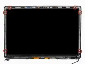
    • Remove the six 2.9 mm Phillips screws securing the LCD panel to the front bezel.

    Hey guys, I need to get the part where the screws are on, whats its name or where could I find it? That part on my Computer broke.... Do you guys think its possible to guet it somewhere?

    diegoantegr31 -

  33. tyeff6iOHEwWEANM
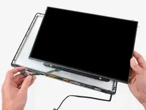
    • Pull the LCD toward the top edge of the display to slide the circuitry along its lower edge out of the recess in the aluminum display assembly.

    • It may be helpful to use one hand to feed the display data cable through its channel in the aluminum display assembly as you pull the LCD toward the top edge of the display with the other hand.

  34. f4eVYJDP1N4sf2Pl
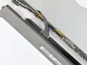
    • Peel the piece of tape covering the display data cable connector away from the edge closest to the LCD.

  35. dv1UTwkhRsoJkLQS
    dv1UTwkhRsoJkLQS
    pVKp3v5IeLxeyfR3
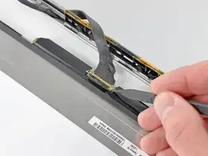
    • Use the tip of a spudger to flip up the thin steel retaining clip securing the display data cable to its socket on the LCD.

    • Pull the display data cable straight away from its socket on the LCD.

    • Lift the LCD out of the display assembly and set it aside.

    • If you are replacing the LVDS/display data cable, simply de-route it from its slot cut into the display casing.

    Danke für das Bereitstellen der Anleitung dadurch konnte ich mein MacBook nach 12 Jahren Einsatz, für die nächsten Jahre fit machen.

    Thanks you for providing this Manuel. It helped me, after 12 year of use to make my MacBook fit for the coming years.

    Albert Zweistein -

Conclusion

To reassemble your device, follow these instructions in reverse order.

Andrew Bookholt

585795 Reputation

9 comments

General : Is there instruction available if you have the anti-glare displays? Or do you officially recommand to change the LCD AND THE GLASS, if we want to keep the anti-glare displays? Can we order the anti-glare displays here? Thanks! =)

ginacouture -

I have a Macbook Pro Unibody 15" (2009) can I switch the whole display and lid with a Macbook Pro 15" (2011)and is the airport card piece for both models in the display?...

MichaelJrRekson -

No, you can’t, because of the camera cable connector, different from the 2011 model.

Fran Werttt -

Where can i get the metal frame that runs through the LCD assembly.

Brayan Almonte -

Same question for me!

Fran Werttt -

Its not a replaceable part

Dan -
Where is wifi module and its antenna?

vniyazov -

Both are well hidden! They are located within the Black Clutch cover within the lid assembly.

Dan -
in Step 15 i think I may have damaged the logic board while pull the cable out. Is there a fix for this?

thrandall -