Introduction

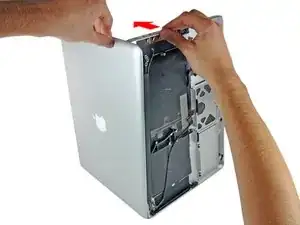
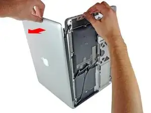
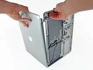
Use this guide to replace the upper case on Anti-Glare Models.

  1. YkoEfqbWbrNPgNSB
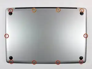
    • Remove the following ten screws securing the lower case to the upper case:

    • Seven 3 mm Phillips screws.

    • Three 13.5 mm Phillips screws.

  2. KmDGlwcxPu6ph3sm
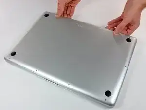
    • Using both hands, lift the lower case near the vent to pop it off two clips securing it to the upper case.

    • Remove the lower case and set it aside.

  3. LHeE6iVx3STyDO3D
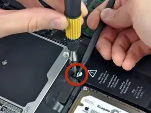
    • Three Pentalobe screws secure the battery to the upper case. They can be removed with this special driver.

    • If you don't have a Pentalobe driver, a 1.5 mm flathead screwdriver can be used in a pinch. Be sure the head of your flathead screwdriver fits snugly across two of the five "points" of the screw head before trying to break the screw free, as a loose fit will easily strip the screw head.

    • If the head of your screwdriver fits too loosely, find a bigger bit and file it down until it fits snugly before proceeding.

    • You do not necessarily have to follow steps 3-7 to remove the battery in order to replace the hard drive. However, it is recommended to remove all power sources from electronics before working on them.

    It really depends on how thick the 1.5 mm flathead screwdriver is. I tried a low-cost tool and almost destroyed the screw. So be carefull

    Paul -

    Unfortunately, when I added a second hard drive via these instructions, all went well but Bluetooth is now MIA. Can anyone help?

    Peter Payne -

    I agree...

    I have bought a used MacBook Pro, when problems arise, opening Corps was trying to turn the screw, but with poor quality could not turn a screwdriver, only to ruin the screw. Try to buy ifixit Screwdriver set. Good luck to all and thank you ifixit team for such assistance as ifixit.com. Thank you.

    remjok -

  4. xGAhgZZyYYcDTHGa
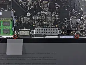
    • Remove the two exposed five-point Pentalobe screws along the top edge of the battery.

    The screws holding my battery were all worn out since an earlier removal. So instead of ruining them even more I put some saran wrap on the tip of my pentalobe driver and gently unscrewed them.

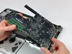
    magnus -

    I have a problem with these screw. They a completly warn and I need some new ones to fix the new Battery.

    Does anyone know which thread it is and which length?

    alexanderleith -

  5. Cu1rp51DpHW16GLl
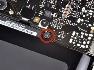
    • Use the tip of a spudger to bend back the finger of the "Warning: Do not remove the battery" sticker while you remove the five-point Pentalobe screw hidden underneath.

  6. QphNb6fJqTBD2cYF
    QphNb6fJqTBD2cYF
    cdkwbvUvHl3QeCJg
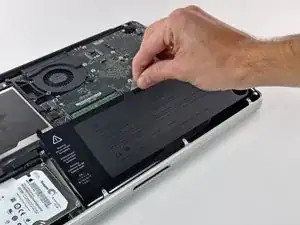
    • Lift the battery by its plastic pull tab and slide it away from the long edge of the upper case.

    • Do not try to completely remove the battery just yet.

  7. BQ1JtoRMPS3hs3VU
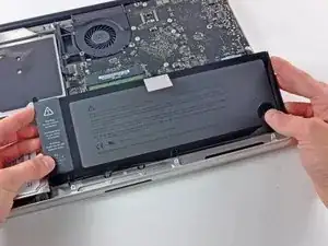
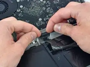
    • Tilt the battery back enough to access the battery cable connector.

    • Pull the battery cable connector away from its socket on the logic board and remove the battery from the upper case.

    • If you're installing a new battery, you should calibrate it as soon as possible.

  8. ns5TexJKqYK5iUaQ
    ns5TexJKqYK5iUaQ
    hp1G6nKuI42DO3Jf
    rETe21ouZIErIsHq
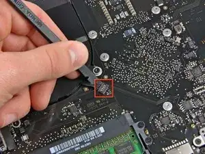
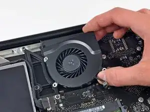
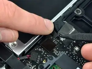
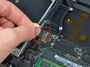
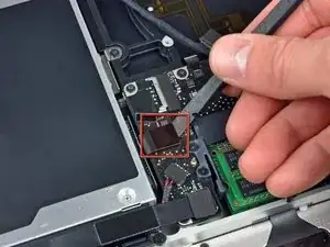
    • Use the flat end of a spudger to pry the fan cable connector up off its socket on the logic board.

    • It is useful to twist the spudger axially from beneath the fan cable wires to release the connector.

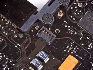
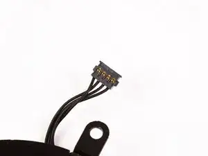
    • The fan socket and the fan connector can be seen in the second and third pictures. Be careful not to break the plastic fan socket off the logic board as you use your spudger to lift the fan connector straight up and out of its socket. The layout of the logic board shown in the second picture may look slightly different than your machine but the fan socket is the same.

  9. P3dpJgPkPN3qyHE6
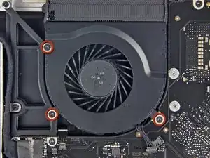
    • Remove the three identical T6 Torx screws securing the fan to the upper case.

    donde podria encontrar el conector que lleva el cableado del ventilador?

    se me rompio el conector del cableado y solo quiero cambiarle el conector ya que el ventilador funciona.

    Un saludo y gracias

    Garikoitz -

  10. 6tcgud1sGBObf6KM
    • Lift the fan out of the upper case.

  11. K23yLvthRBjDdO2A
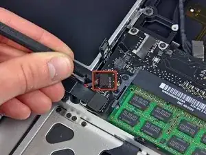
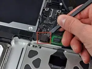
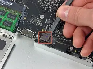
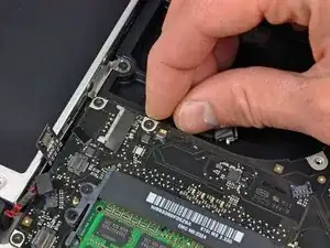
    • Apple sticks a small strip of clear plastic with adhesive applied to one side to the logic board behind the camera cable connector to keep it in its socket. When moving it out of the way, be sure not to break any surface-mount components off the logic board.

    • Hold the end of the cable retainer down with one finger while you use the tip of a spudger to slightly lift the other end and rotate it away from the camera cable connector.

    Bear in mind that the “Camera Cable” is also the cable connecting the logic board to the Wifi Airport Card, at least on the Glossy model (not sure about the Anti-Glare model). The Wifi Airport Card is located under the display’s clutch cover, and requires removing the display in order to access it.

    lilliputian -

  12. 6BIDHaTld4NGJQnb
    • Disconnect the camera cable by pulling the male end straight away from its socket.

    • Pull the connector parallel to the face of the logic board, not straight up.

  13. aClCQnfqqpl336B5
    • Use the flat end of a spudger to pry the optical drive cable connector up off the logic board.

  14. GImSs4UWau4DABDI
    • Using the flat end of a spudger, pry the subwoofer connector straight up off the logic board.

    Be very careful to not get under the connector base on the logic board. You can pull it off. It is only secured by weak surface mount solder.

    jimmarsen -

    I second that sentiment. The connector base is slightly elevated off the logic board, and it is easy to get your tool under that instead of the male plug you're trying to disconnect. I pulled mine off, and for now the speakers are tinny.

    Gruberg -

    I can't plug the subwoofer cable back. It seems to be too big. I have no idea, what I can do? Any ideas?

    Tom Pilath -

  15. 3AiEHAMUhhY4nWQF
    • Use the flat end of a spudger to pry the hard drive/IR sensor cable connector up off the logic board.

  16. K3QoNLwuVBPPVLEb
    K3QoNLwuVBPPVLEb
    hqwkDWtAfsoELR5w
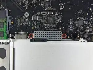
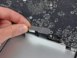
    • Remove the two 1.5 mm Phillips screws securing the cable cover to the logic board.

    • Lift the cable cover out of the upper case.

  17. pcIFLqNMibbltQnc
    • Use a spudger to pry the trackpad flex ribbon cable connector up off the logic board.

  18. 3XJxCAYoNNfSCncB
    • Using the tip of a spudger, flip up the keyboard ribbon cable retaining flap.

    • Pull the keyboard ribbon cable straight out of its socket.

    I dont need the spudger for that!

    Tom Pilath -

  19. CeDcnIGHCxpxDjpG
    • Use a spudger to pry the battery indicator ribbon cable connector up off the logic board.

  20. IxRTRUDAbVGOCIXq
    IxRTRUDAbVGOCIXq
    NVIx3eTSNC6PV6fc
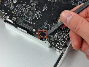
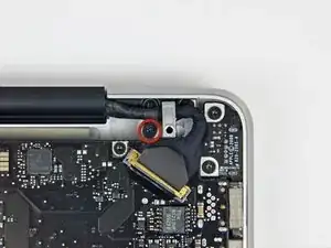
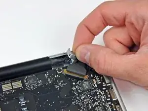
    • Remove the single 7 mm Phillips screw securing the display data cable retainer to the upper case.

    • This screw may remain captive in the display data cable ground loop. If replacing the display, be sure to transfer this screw to the new unit.

    • Remove the display data cable retainer from the upper case.

  21. aFnoZBysPSndru2F
    aFnoZBysPSndru2F
    UBMReUDatZI6Bhvn
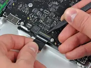
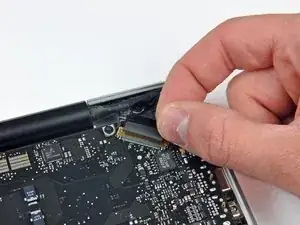
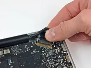
    • Grab the plastic pull tab secured to the display data cable lock and rotate it toward the DC-in side of the computer.

    • Pull the display data cable connector straight away from its socket.

    • Make sure to pull the connector parallel to the face of the logic board, not straight up from its socket.

  22. TrjGa6fsnBCZ3WeM
    TrjGa6fsnBCZ3WeM
    LMCfYsLLXG63dxBK
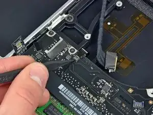
    • Using the tip of a spudger, flip up the keyboard backlight ribbon cable retaining flap.

    • Pull the keyboard backlight ribbon cable straight out of its socket.

  23. ev5sOaeNaoSa2Q5W
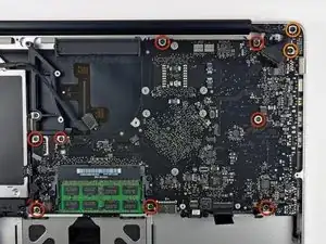
    • Remove the following screws:

    • Eight 3.5 mm T6 Torx screws securing the logic board to the upper case.

    • Two T6 Torx screws securing the DC-In board to the upper case.

    • Do not remove the logic board yet! There are connectors attached to the underside of the logic board that must first be disconnected.

  24. UnKaIEbOf6qEOAm1
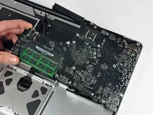
    • Carefully lift the logic board assembly from the left side and work it out of the upper case, minding the port side that may get caught during removal.

    • Do not entirely remove the logic board yet!

    • Ensure that the logic board is free from all connections to the upper case (except the battery connector) before proceeding.

    I,ve done everything up to this step but my logic board still seems to be connected (by glue i think) to the black plastic underneath and the black frame that can't be unscrewed. Any idea how to get past this?

    Josh -

    For step 24, the same thing happened to me as did to Josh. The heat pipe had bonded with the plastic film which protects the back of the keyboard. By using a spudger i was able to pry at the area where the two were attached. I don't think this is intentional, they just melt together.

    Matt -

    Same happened to me. Matt is right. I gained extra clearance by removing both RAM modules. Then used the spudger. Sounds cracky but it´s all fine.

    Diego Trueba -

  25. XBPBI6QVivSUHBNw
    XBPBI6QVivSUHBNw
    Sfrm6HbTXMeucPPq
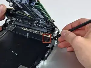
    • Lift the logic board enough to gain clearance and use a spudger to pry the microphone up off the upper case.

    • Slide the logic board away from the port openings and lift the assembly out of the upper case.

    • Before reinstalling the logic board, it is easiest to press the microphone down into its housing in the left speaker to keep it in place.

  26. kR2Ccqmoynb4eJRK
    kR2Ccqmoynb4eJRK
    pGJcqkboUdSfVqlq
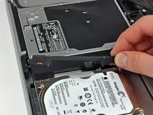
    • Remove the two Phillips screws securing the hard drive bracket to the upper case.

    • These screws are captive to the hard drive bracket.

    • Remove the hard drive bracket from the upper case.

  27. AgMgoo1kB1ZNIEiJ
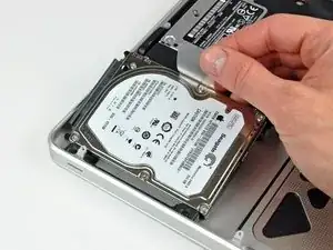
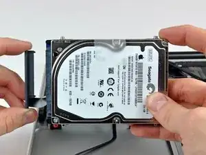
    • Lift the hard drive out of the upper case by its plastic pull tab, minding the cable attaching it to the computer.

  28. DNNGOYxpRGlrcKER
    DNNGOYxpRGlrcKER
    RU2i2tsxi2PDHx3b
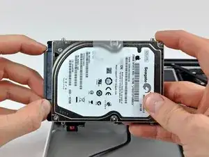
    • Remove the hard drive from its cable by pulling the cable connector straight away from the drive.

  29. pKfLFGVEqeyLRwLg
    pKfLFGVEqeyLRwLg
    I5XeEbwhI1BOIHc5
    Xg5OZ5aHnODFlAKP
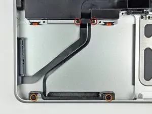
    • Remove the following four screws securing the hard drive and IR sensor cable to the upper case:

    • Two 1.5 mm Phillips screws.

    • Two 4 mm Phillips screws.

    • Slide the hard drive and IR sensor bracket away from the edge of the upper case.

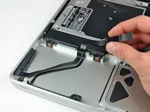
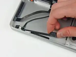
    • Carefully peel the hard drive and IR sensor cable from the upper case.

    • Remove the hard drive/IR sensor cable from the upper case and set it aside.

  30. KWT11QcmbYpNrB2x
    KWT11QcmbYpNrB2x
    buW6myOQnpdNybXf
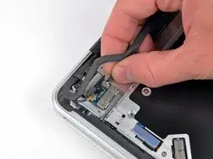
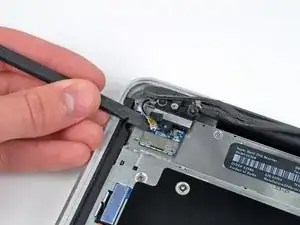
    • Disconnect the Bluetooth cable by pulling the male end straight away from its socket.

    • Use the flat end of a spudger to carefully pry the AirPort antenna off its socket on the AirPort card.

    • Pull the connector parallel to the face of the logic board, not straight up.

  31. mQ6MJhEKA1PDnLqx
    mQ6MJhEKA1PDnLqx
    GupXkqrdEiBVgQXJ
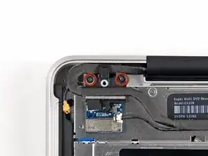
    • Remove the two 8 mm Phillips screws securing the Bluetooth/camera cable retainer to the upper case.

    • One of the screws may remain captive in the Bluetooth/camera cable ground loop. If replacing the display, be sure to transfer this screw to the new unit.

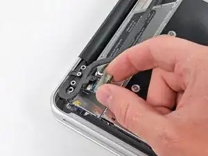
    • Lift the AirPort board/cable retainer assembly out of the upper case.

  32. MAVRBKRJqdWBxceX
    MAVRBKRJqdWBxceX
    UHXwdGlYUddOsyvA
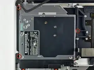
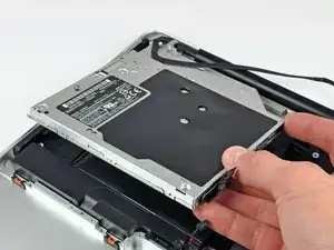
    • Remove three 3.5 mm Phillips screws securing the optical drive to the upper case.

    • Lift the optical drive from its left edge and pull it out of the computer.

  33. kASM1gWLAHCgZsRp
    kASM1gWLAHCgZsRp
    VXPUCECjD4QaXYCY
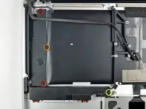
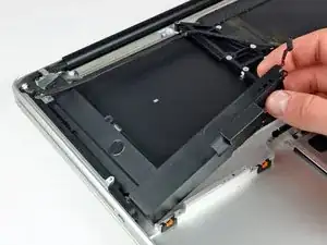
    • Remove the following four screws securing the subwoofer and right speaker to the upper case:

    • Two 3.2 mm Phillips screws.

    • One 2.6 mm Phillips screw.

    • One 5 mm Phillips screw.

    • Lift the subwoofer and right speaker assembly out of the upper case.

  34. tMMjSFkQk5HLZQCF
    tMMjSFkQk5HLZQCF
    ccXU6oQNNMXJNibJ
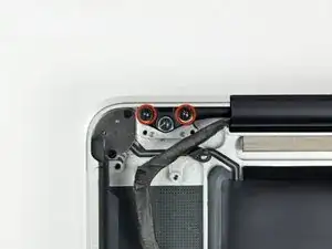
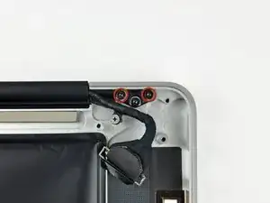
    • Remove two outer 6 mm Torx screws securing each side of the display to the upper case (4 screws total).

    • We intentionally have you leave one screw in each hinge to aid in the following steps.

  35. 5cW2IVMjAvv2iM3Z
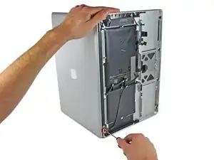
    • Open your MacBook Pro so the display is perpendicular to the upper case.

    • Place your opened MacBook Pro on a table as pictured.

    • While holding the display and upper case together with your other hand, remove the 6 mm Torx screw from the lower display bracket.

  36. 15iiJX2wrZ3phtHM
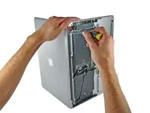
    • Be sure to hold the display and upper case together with your other hand. Failure to do so may cause the freed display/upper case to fall, potentially damaging each component.

    • Remove the last remaining 6 mm Torx screw securing the display to the upper case.

  37. GaLWmPAIqImJlRyJ
    GaLWmPAIqImJlRyJ
    t2OUPWKyL4uT6yNK
    tZPuPsd2is66TMPC
    • Grab the upper case with your right hand and rotate it slightly toward the top of the display so the upper display bracket clears the edge of the upper case.

    • Rotate the display slightly away from the upper case.

    • Lift the display away from the upper case, minding any brackets or cables that may get caught.

Conclusion

To reassemble your device, follow these instructions in reverse order.
Andrew Bookholt

585795 Reputation

0 comments