Introduction
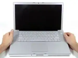
Replace a broken LCD rather than replacing your entire display.
-
-
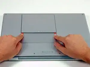
Use your fingers to push both battery release tabs away from the battery, and lift the battery out of the computer.
-
-
-
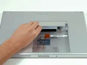
Lift the memory door up enough to get a grip on it, and slide it toward you, pulling it away from the casing.
-
-
-
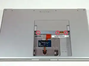
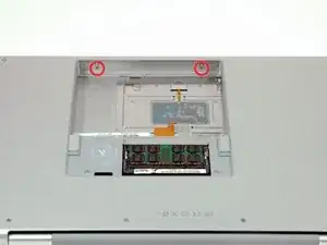
Remove the following 6 screws:
-
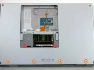
Two 10 mm T6 Torx screws on either side of the RAM slot.
-
Four 14.5 mm Phillips screws along the hinge.
-
-
-
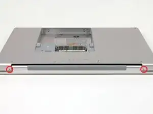
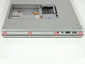
Rotate the computer 90 degrees and remove the two Phillips screws from the rear of the computer.
-
-
-
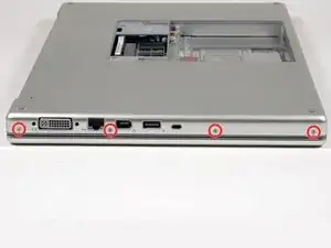
Rotate the computer 90 degrees again and remove the four Phillips screws from the side of the computer.
-
-
-
Lift up at the rear of the case and work your fingers along the sides, freeing the case as you go. Once you have freed the sides, you may need to rock the case up and down to free the front of the upper case. This stage can be quite tricky. Over the DVD reader are 4 tabs set back which pull out vertically.
-
Note that the two small tongues on the left hand front of the upper case may bend while you remove the upper case. When re-installing, you may need to bend them back to fit in the grooves in the lower case.
-
-
-
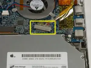
Disconnect the trackpad and keyboard ribbon cable from the logic board, removing tape as necessary.
-
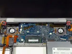
Remove the upper case.
-
-
-
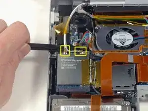
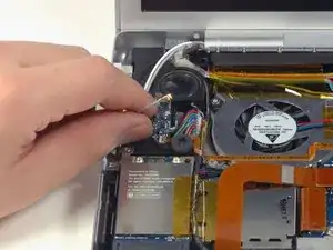
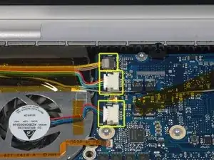
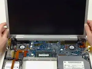
Disconnect the iSight, inverter, and left fan cables from the logic board by gently pulling in the direction of each cable.
-
-
-
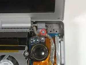
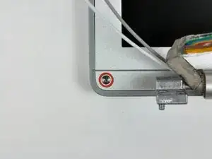
Remove the silver T6 Torx screw securing the ground loop on the display data cable to the casing.
-
-
-
Support the display with one hand while removing the following 3 screws:
-
Two 9.5 mm silver T6 Torx screws with threads on only part of the shaft on the inside of the display hinges.
-
One 9.5 mm silver T6 Torx screw with threads on the entire shaft on the outside of the left hinge.
-
-
-
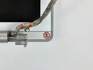
Remove the two 5 mm Phillips screws from the lower left and right corners of the display (two screws total).
-
-
-
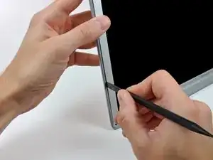
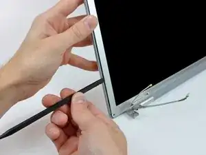
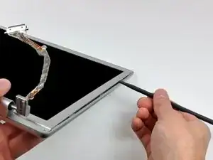
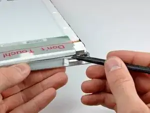
Insert the flat end of a spudger perpendicular to the face of the display between the plastic strip attached to the rear bezel and the front bezel.
-
With the spudger still inserted, rotate it away from the display to separate the front and rear bezels.
-
Work along the left edge of the display until the rear bezel is evenly separated from the front bezel.
-
-
-
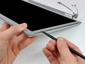
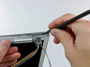
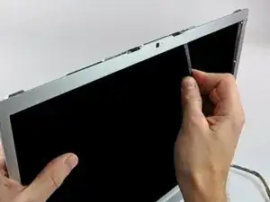
Insert the flat end of a spudger perpendicular to the face of the display between the plastic strip attached to the rear bezel and the front bezel.
-
With the spudger still inserted, rotate it away from the display to separate the front and rear bezels.
-
Work along the right edge of the display until the rear bezel is evenly separated from the front bezel.
-
-
-
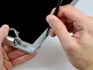
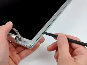
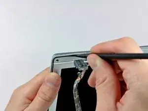
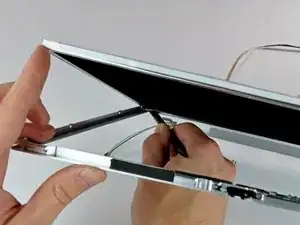
Insert the flat end of a spudger between the front bezel and the plastic strip attached to the rear bezel near the screw holes at the bottom corners of the display.
-
Rotate your spudger toward the rear bezel to separate it from the front bezel.
-
If necessary, enlarge the gap between the lower edge of the rear bezel and the clutch cover until the two components are completely separated.
-
-
-
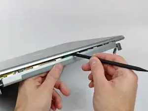
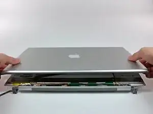
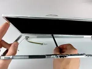
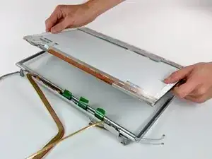
Lift the rear bezel by its bottom edge and rotate it away from the display assembly to separate the top edge.
-
Remove the rear display bezel from the display assembly.
-
-
-
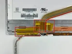
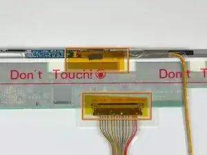
Remove the pieces of yellow kapton tape from the bottom left corner of the display.
-
Remove the pieces of tape securing the display data cable and camera cable to the display.
-
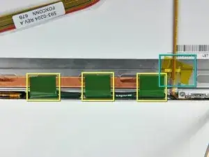
Peel the three green antenna ground straps off the copper tape along the bottom edge of the LCD.
-
Remove the piece of tape securing the camera cable to the LCD.
-
-
-
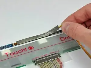
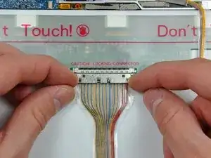
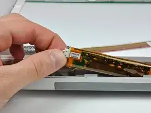
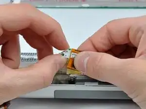
Use the tip of a spudger and carefully flip the ZIF connector bar up to release the before the camera cable.
-
Gently pull the camera cable away from its socket on the camera board.
-
-
-
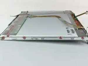
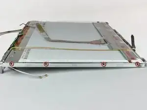
Remove the four black Phillips screws along the left and right edges of the display (eight screws total).
-
-
-
Use the flat end of a spudger to gently lift one of the top corners of the LCD out of the front bezel.
-
-
-
Work your way along the top edge of the LCD, slowly prying the attached steel strip away from the front bezel.
-
-
-
Now that the top edge is free, slightly lift the LCD out of the front bezel for enough room to pry the steel strip along the lower edge of the LCD away from the front bezel.
-
Pry along the lower edge of the LCD until it is freed from the adhesive on the front bezel.
-
-
-
Lift the inverter out of the clutch cover.
-
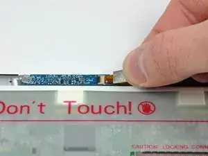
Disconnect the LCD backlight connector from its socket on the inverter board.
-

To reassemble your device, follow these instructions in reverse order.

4 comments
Be aware that replacing the rear bezel without problems depends entirely on gentle handling. There are some aluminum tabs in recesses on the top edge of the rear bezel that do not take kindly to rough handling!
dave -
You would be well advised to buy in some Kapton tape before reassembly, as the old tape tends to split on removal.
dave -
Bravo. Worked like a champ. Excellent write up and really appreciate it. I did it twice today hahahah
Before beginning, I found some small plastic bags and labeled each of the with the location the screws would come from once removed and the appropriate step number. Once the screws were removed I placed them in the labeled bags and did not have to worry about mixing screws up. Also, provided a good way to insure that no steps were skipped in the reverse process
rpbetancourt -