Introduction
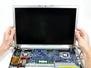
Change out the entire display assembly, including the inverter, Airport antennas, hinges and casing.
-
-
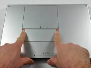
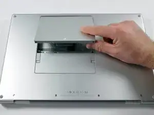
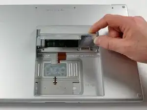
Use your fingers to push both battery release tabs away from the battery, and lift the battery out of the computer.
-
-
-
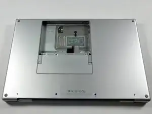
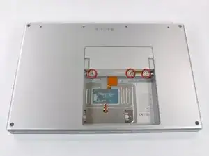
Remove the three identical 2mm Phillips screws from the memory door.
-
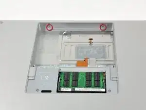
Lift the memory door up enough to grip it and slide it toward you, pulling it away from the casing.
-
-
-
Remove the following 6 screws:
-
Two 10 mm T6 Torx screws on either side of the RAM slot.
-
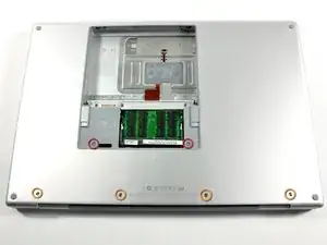
Four 14.5 mm Phillips screws along the hinge.
-
-
-
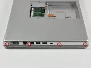
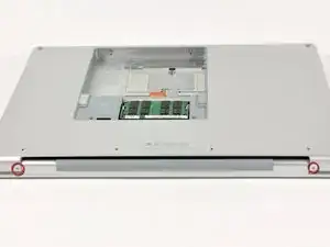
Rotate the computer 90 degrees and remove the two 3.2 mm Phillips screws from the rear of the computer.
-
-
-
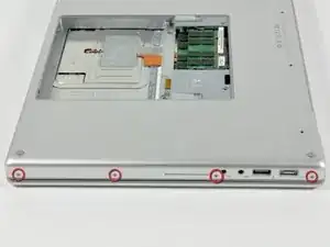
Rotate the computer 90 degrees again and remove the four 3.2 mm Phillips screws from the side of the computer.
-
-
-
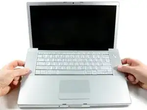
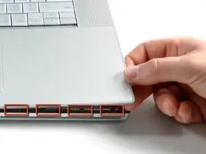
Lift up at the rear of the case and work your fingers along the sides, freeing the case as you go. Once you have freed the sides, you may need to rock the case up and down to free the front of the upper case.
-
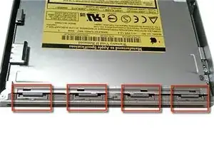
There are four plastic clips above the DVD slot, and another above and to the left of the IR sensor. These clips can be very difficult to disengage without prying. They can also be difficult to re-engage during reassembly.
-
-
-
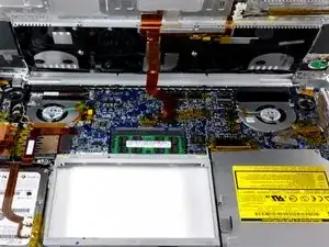
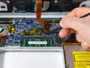
Disconnect the trackpad and keyboard ribbon cable from the logic board, removing tape as necessary.
-
Remove the upper case.
-
-
-
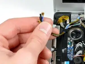
Disconnect the two or three antenna cables attached to the Airport Extreme card. Depending on your model, one of the three cables may be unused and capped with a black shrink tube.
-
-
-
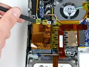
Disconnect the iSight cable from the logic board by sliding the cable to the left and out of its connector.
-
-
-
Support the display with one hand while removing the following screws:
-
One 9.5 mm silver T6 Torx screw with threads on only 3 mm of the shaft on the inside of the display hinges.
-
One 9.5 mm silver T6 Torx screw with threads on the entire shaft on the outside of the left hinge.
-
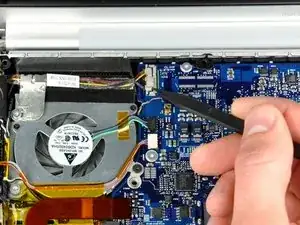
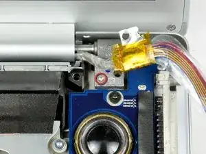
One 9.2 mm full thread T6 Torx screw securing the iSight cable ground loop to the fan.
-
-
-
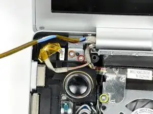
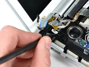
Disconnect the inverter cable from the left I/O board by placing a spudger beneath the cable and lifting up.
-
-
-
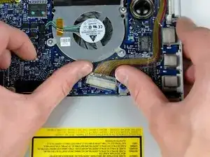
Disconnect the display data cable from the logic board.
-
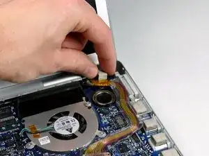
Remove the foam bumper from the top of the right hinge of the display.
-
-
-
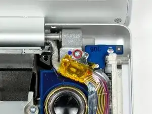
Remove the silver 9.2 mm T6 Torx securing the ground loop in the display data cable to the casing.
-
-
-
Support the display with one hand while removing the following screw:
-
One 9.5 mm silver T6 Torx screw with threads on only 3 mm of the shaft on the inside of the display hinges.
-

To reassemble your device, follow these instructions in reverse order.

2 comments
Excellent job here and iFixit of course gets a nod with the author Walter Galan. It was reassuring to take apart. Having been inside the ole 2008 Penryn beast no biggie. But following the steps here for removing the screen was a treat. Better yet, having the photos to make sure the cables laid down properly when being reattached was reassuring. Thank you Walter!
Completed this in just over 30 minutes and not rushing.
Howdy! I can’t get my macbook to power up after the screen replacement. Anything simple I should be looking for?
emholden -
Before start, make a clone of your old HD into the new one, if you don't want to initiate a fresh copy. (Carbon Copy software is good).
ColmillodeChile -
Besides using WD 500GB models, are the WD 640GB and WD 750GB (the 9.5mm thickness model) good to go for? I am still considering as I have heard from other websites on the computer does not draw enough power to power up the 640 and 750 as it has the clicking sound and the rainbow keeps appearing. Anyone has install one before yet?
Please advice. Appreciated! Thanks a million to all the Mac gurus out there!
Danny Lim -