Introduction

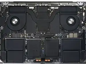
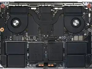
Use this guide to remove the logic board in your MacBook Pro 14" 2021.

This is a prerequisite-only guide! This guide is part of another procedure and is not meant to be used alone.

  1. mMZ5rxjcvUWQkEXG
    mMZ5rxjcvUWQkEXG
    WJQiPlJWtdVFUKPE
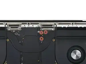
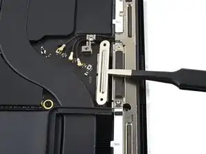
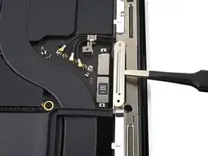
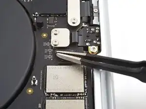
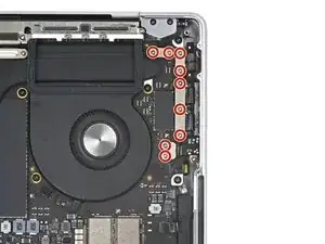
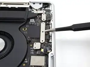
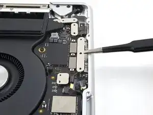
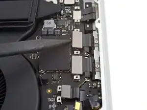
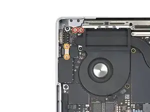
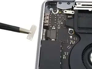
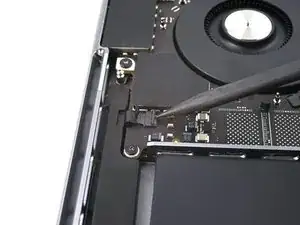
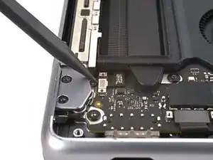
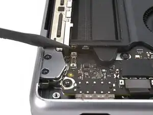
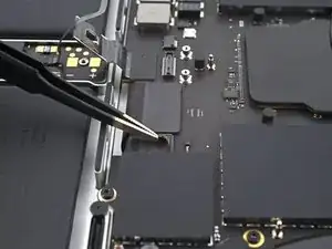
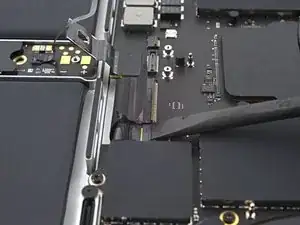
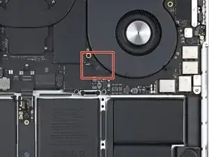
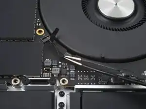
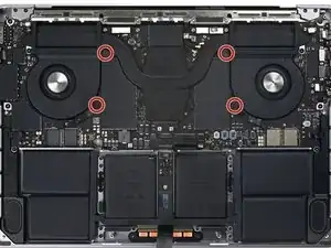
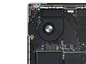
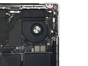
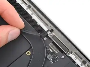
    • Use a T3 Torx screwdriver to remove the three 2.1 mm screws securing the antenna board bracket and coaxial cable cover to the frame.

  2. yhd2TYMiMHNLvVlq
    yhd2TYMiMHNLvVlq
    MQPANHn3TAFOrjZq
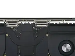
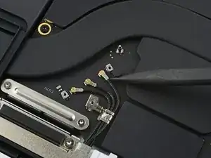
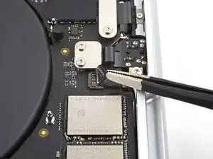
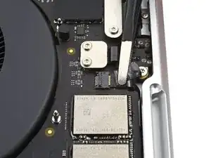
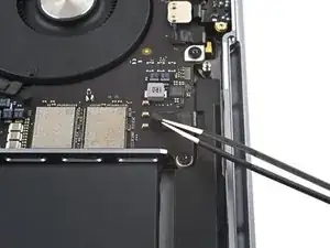
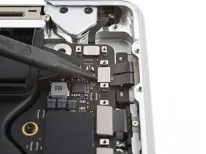
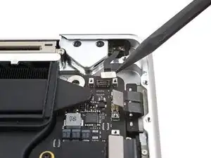
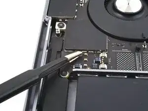
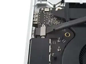
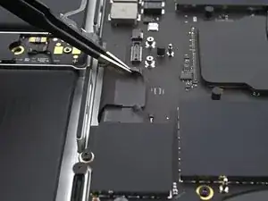
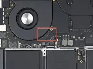
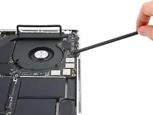
    • Use tweezers, or your fingers, to remove the cover on top of the antenna bar's coaxial cables.

  3. rKLLcQuUVYwLqFuC
    rKLLcQuUVYwLqFuC
    THymLDTfhmVtFVNO
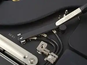
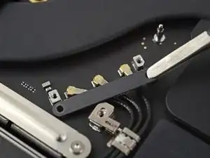
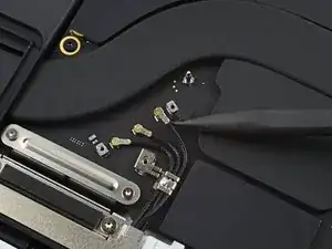
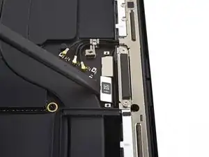
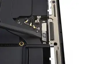
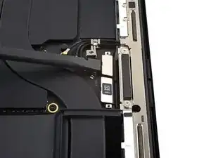
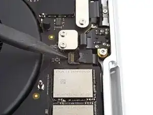
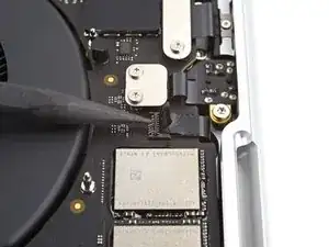
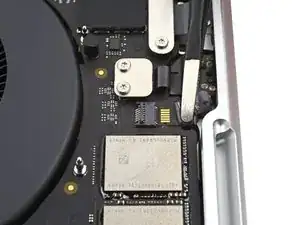
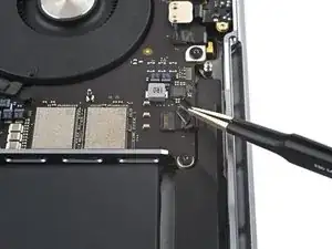
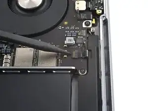
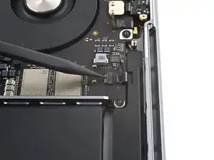
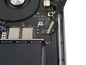
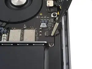
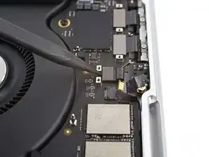
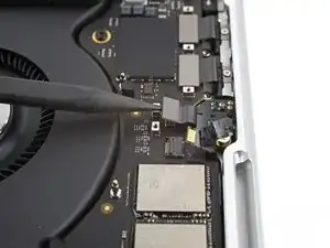
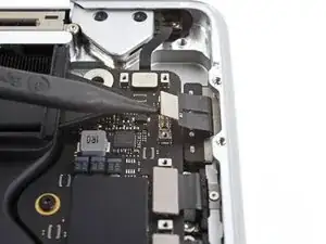
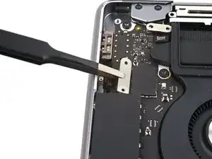
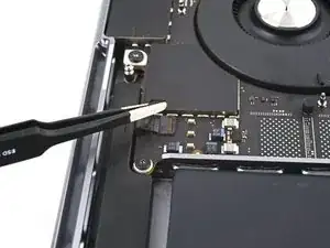
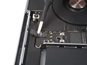
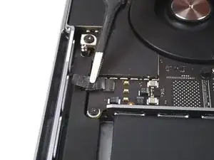
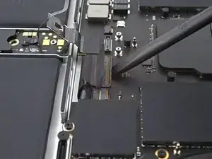
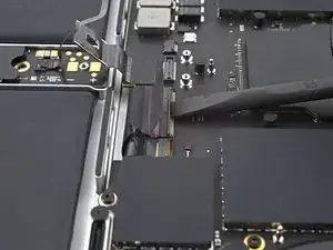
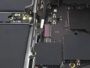
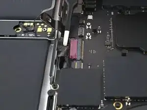
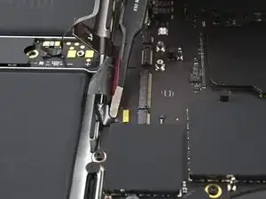
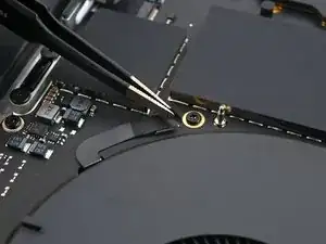
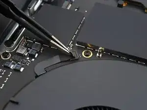
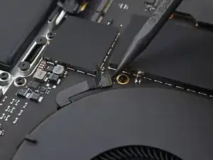
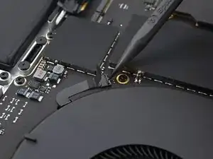
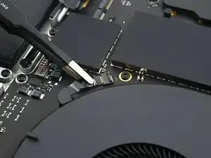
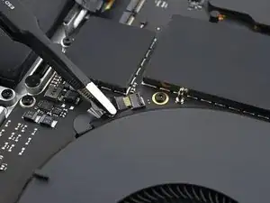
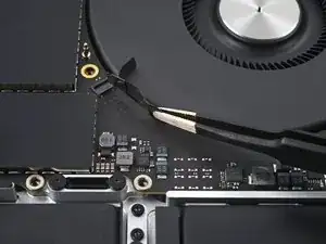
    • Use the tip of a spudger to pry up and disconnect the antenna bar's coaxial cable.

    • Repeat for the two other cables.

    • During reassembly, these can be tricky to reconnect. Hold each connector in place over its socket and press down with the flat end of a spudger. The connector should snap into place.

  4. wJqiVVv1y44wM1DA
    wJqiVVv1y44wM1DA
    AVfmWrPYUkdFd1uC
    • Use a T3 Torx driver to remove the four 2.1 mm screws securing the screen cable covers.

    These are not T5 screws (that'd be the cable cover above these two), but T3 screws.

    Sander -

  5. fUyVg6qQaZZuWrTm
    fUyVg6qQaZZuWrTm
    DcryJPmKWFrBthXO
    • Use tweezers, or your fingers, to remove the two screen cable covers from the logic board.

  6. T5dHUDiAW5KhuORW
    T5dHUDiAW5KhuORW
    a2UBQFd6jn1ZRYgi
    pXBtOLXKl22qTYCa
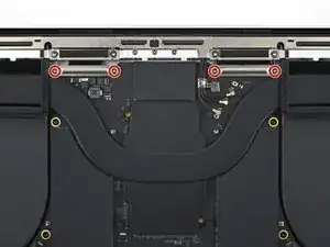
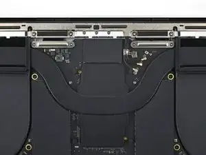
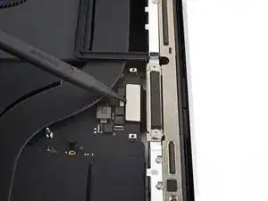
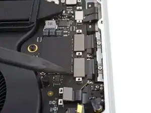
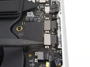
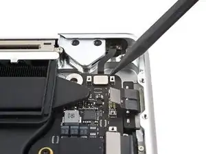
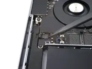
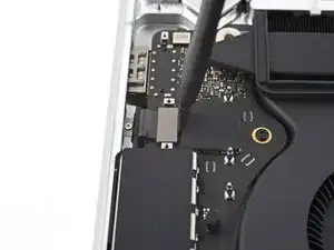
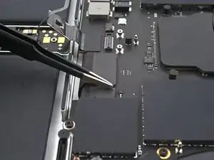
    • Use the flat end of a spudger to pry up and disconnect the right-most screen cable press connectors secured to the logic board.

  7. XmqfZnFQlJBDQcdn
    XmqfZnFQlJBDQcdn
    E33OJIIWbY1e5lZQ
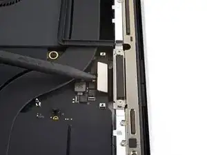
    • Repeat the previous disconnection process for the remaining press connector at the top left of the logic board.

    • Don't pry against the surface-mounted components near the press connector.

  8. XUsHDd5PItgiwqGc
    XUsHDd5PItgiwqGc
    CUGVQNcSLJRUmBFf
    jJ1noLVTNdKK21AX
    • Peel back any tape covering the microphone cable connector.

  9. huLPTQof2QdYhlKh
    huLPTQof2QdYhlKh
    EQtpt4vuiLYaleIl
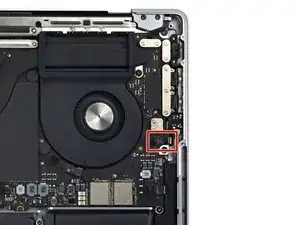
    • Use a spudger to gently pry up the locking flap on the ZIF connector for the microphone cable.

  10. I1HqZiiRFBn2rZ1o
    I1HqZiiRFBn2rZ1o
    M5NJKwyfGBQj4phB
    • Disconnect the microphone cable by sliding it out from its socket on the logic board.

  11. DfUSWdodKxMhCVId
    DfUSWdodKxMhCVId
    2jKVuJYwmKuJ1xJ5
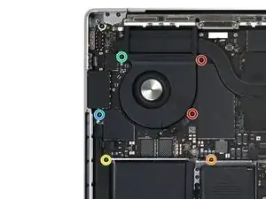
    • Use a T3 Torx driver to remove the nine 2.1 mm screws securing the right cable covers to the frame:

  12. WRNwTIPxZrQcDWsi
    WRNwTIPxZrQcDWsi
    sw3KcOWZ3lxIM4mC
    • Use tweezers, or your fingers, to remove the five right cable covers.

    You state "five", but only show FOUR in your highlights.

    elijah dorman -

  13. PuBlx3Mc4JkFjxd4
    PuBlx3Mc4JkFjxd4
    M4reLvECTiZRS3gl
    • Peel back any tape covering the right speaker cable.

  14. jEGkrTWfKARiRRH4
    jEGkrTWfKARiRRH4
    TDYr33aKIAOf15J1
    • Use a spudger to gently pry up the locking flap on the ZIF connector for the right speaker cable.

  15. 4mSQoxo1LZmJfuIs
    4mSQoxo1LZmJfuIs
    GlSAI44K6Tpw5vIx
    • Disconnect the right speaker cable by sliding it out from its socket on the logic board.

  16. ZFEOF2DXdBdSPKoM
    ZFEOF2DXdBdSPKoM
    QLNkDkjDTKSBlWMS
    • Use a spudger to pry up and disconnect the headphone jack's press connector.

  17. 6bWFLbL4EDV535eV
    6bWFLbL4EDV535eV
    VGy2PiNvxQGceDaX
    QYHHJZ3ayPHrlQgt
    • Use a spudger to pry up and disconnect the right USB-C ports' press connectors.

  18. ZRn6lsUEM6BVIWno
    ZRn6lsUEM6BVIWno
    hFeXWmQFCV3UAm6Q
    • Use a spudger to pry up and disconnect the MagSafe port's press connector.

  19. Z665sDMVtgnSGbvR
    Z665sDMVtgnSGbvR
    wpLgDVrAwipWEGH4
    • Use a spudger to pry up and disconnect the lid angle sensor's press connector.

  20. QdRf2fJ5nvZVybnb
    QdRf2fJ5nvZVybnb
    vbZXiOIrDCIvEuHB
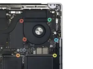
    • Use a T3 Torx driver to remove the four screws securing the left cable covers to the frame:

    • Two 2 mm screws

    • Two 2.1 mm screw

  21. 2L6ZGTVkC3qSkDq1
    2L6ZGTVkC3qSkDq1
    nVPWyJCnQ1ViRJHg
    • Use tweezers, or your fingers, to remove the two left cable covers.

    Habe das obere Kabel hier leider zerstört. Könnt Ihr mir sagen, für was das ist und ob ich meinen Mac weiter benutzen kann/darf/soll?

    Ray -

  22. uFy4sA52LPiyebnF
    uFy4sA52LPiyebnF
    NTSqa6cIVB2IhmTi
    • Peel back any tape covering the left speaker cable.

  23. ukFeo2cqAT5mLUEM
    ukFeo2cqAT5mLUEM
    x2YyHIWp3rTfUQmS
    • Use a spudger to gently pry up the locking flap on the ZIF connector for the left speaker cable.

  24. XhuKlr42ALKwF3ud
    XhuKlr42ALKwF3ud
    MpFMvToCmLLHenU3
    • Disconnect the left speaker cable by sliding it out from its socket on the logic board.

  25. Fpb3PS2qBjPOGbiZ
    Fpb3PS2qBjPOGbiZ
    jRDyCNWY5BTQdJJW
    • Use a spudger to pry up and disconnect the left USB-C port's press connector.

  26. jjav3KJxNIhLoSmv
    jjav3KJxNIhLoSmv
    atQNZy6nNekRn2yM
    • Use a spudger to pry up and disconnect the Touch ID sensor's press connector near the top left of the device.

    • The Touch ID sensor cable is adhered to the frame. If the adhesive doesn't separate when you disconnect the press connector, slide an opening pick under the cable to separate it.

    The TouchID cable is incredibly delicate and prone to tearing; use caution when bending it with tools.

    Sander -

  27. Iroju51ubUMqWlwJ
    Iroju51ubUMqWlwJ
    YGIc6G6SZMp6FHFR
    RZSakKOCbrvDMbaR
  28. MlXLTEjakHYHAjRr
    MlXLTEjakHYHAjRr
    2YEogySHV4SNDDtP
    UGG1rYulGRNARgOt
    • Use a spudger to gently pry up the locking flap on the ZIF connectors for the keyboard cables.

  29. fMxtDssND5PWchMC
    fMxtDssND5PWchMC
    jpqGrqlTuFGbjMgK
    AYTJJBNNRGdOLKrG
    • Disconnect the keyboard and keyboard backlight cables by sliding them out from their sockets on the logic board.

  30. CVSrQJ3TTL1jHKIF
    CVSrQJ3TTL1jHKIF
    y4Q4XpbqVCfeiHCu
    SVRmCoGaAtKGljpA
    • Peel back any tape covering the right fan cable connector.

  31. tFyrq1a6oT2RYkMV
    tFyrq1a6oT2RYkMV
    pk3xYlnLtFKUMpDp
    • Use a spudger to gently pry up the locking flap on the ZIF connector for the right fan cable.

  32. DXsNNDWDCIe5hMio
    DXsNNDWDCIe5hMio
    bmG4tyWDCV1PCOL6
    • Disconnect the right fan cable by sliding it out from its socket on the logic board.

  33. mafaS4hoBrrldagh
    mafaS4hoBrrldagh
    oh2DeJcRJXSJCkmo
    • The right fan cable is lightly adhered to the logic board.

    • Pull the fan cable away from the logic board with tweezers to separate the adhesive.

    • The fan cables are incredibly delicate and prone to tearing; use caution when bending them with tools.

  34. eoRafE6PLsaHWMTW
    eoRafE6PLsaHWMTW
    KFIvQSeFbTQtYvIY
    • Repeat the previous disconnection and reposition procedure for the left fan.

  35. gAkHbL1oHrGiZVHu
    gAkHbL1oHrGiZVHu
    HRuPDcYiLuCRnoW2
    • Remove the four black screw covers from the logic board.

  36. bL3UWMgmleLGRYnq
    bL3UWMgmleLGRYnq
    xEtDInKJmVfFVdYw
    YEsCGHA5OQSXKbWt
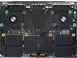
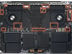
    • Use a T5 Torx driver to remove the 12 screws securing the logic board:

    • Four 3.6 mm screws

    • Two 4.5 mm screws

    • Two 5.2 mm screws

    • Two 3.8 mm screws

    • Two 3.9 mm screw

    Length of the "green" screws please

    Luc Chandonnet -

    Hi Luc.

    Thank you for the comment! I have adjusted the guide accordingly.

    Alex Diaz-Kokaisl -

    Erase the reference to the blue screw next to the SD card slot - it is not T5-3.9 like its opposite counterpart, it is T6-5.7mm as shown in the next panel

    Dave C -

    Left Blue screw is T6 on my system

    elijah dorman -

  37. 5PdH2BB4HpA1ZsWN
    5PdH2BB4HpA1ZsWN
    CLNZM3rHXQRAJwxe
    EnXIsmGjIIluGFpS
    • Use a T6 Torx driver to remove the three screws securing the logic board:

    • Two 4.7 mm screws

    • One 5.7 mm screw

    Orange Screw is already referenced above as the left Blue screw in step 56.

    elijah dorman -

  38. guNSXsWIRmk1FcVM
    guNSXsWIRmk1FcVM
    ByVZUASwcMVGUENh
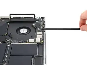
    • Insert a spudger between the right side of the logic board and the frame.

    • Pry up with the spudger to release the logic board from its clips.

    There's a missing step to pry up the adhesive rubber bits holding the heatsinks to the fan.

    elijah dorman -

  39. AIbNeE1pUjTPLsSA
    AIbNeE1pUjTPLsSA
    qTCHc3vDRYHHiolF
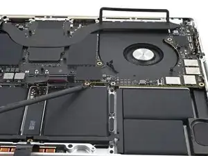
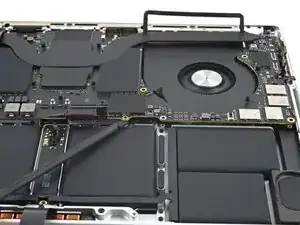
    • Insert a spudger between the bottom of the logic board and the frame.

    • Pry up with the spudger to release the logic board from its clips.

  40. ElA1wLUeH5MaVPJQ
    ElA1wLUeH5MaVPJQ
    NsudbUgAmD3RdSmU
    6BvoRNyIaX1GcydA
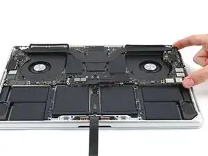
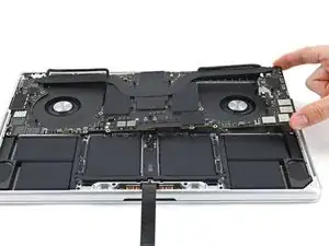
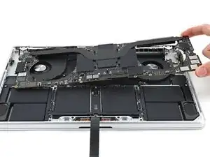
    • Gently lift up the logic board by its right side to release it from its alignment pegs.

    • If it feels like it's not coming out, check that all the cables are disconnected.

    • Pull the logic board away from the left side of the device to separate the HDMI and SDXC ports from their slots in the frame.

    • Remove the logic board.

  41. fkNRHEcDAACYZrQL
    fkNRHEcDAACYZrQL
    5XSeMp6RSfCfSTD1
    kg23fMSLDOgqwJHP
    • During reassembly, perform the following:

    • Make sure all 17 connectors are above the logic board before securing it back into the frame.

    • If you're having trouble positioning the connectors, use tape to keep them out of the way.

    • Hold the rubber spacers out of the way so the fins can drop into their recesses.

    • When reinstalling the logic board, insert the left side first to reposition the HMDI and SDXC ports.

    • Use your fingers to slightly compress the HDMI port to fit it into its recess. Otherwise, the logic board won't sit correctly.

    I count 2 connectors on the left, 6 on the top (counting all three antennas as one), 6 on the right, 2 on the bottom, and 2 in the center (for each fan) giving a total of 18

    elijah dorman -

Conclusion

To reassemble your device, follow these instructions in reverse order.

Alex Diaz-Kokaisl

Member since: 16/01/22

117875 Reputation

0 comments