Introduction

Use this guide to completely replace your upper case.

  1. dOyroxuUBfNu1T4K
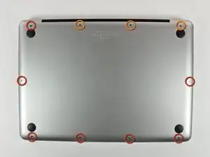
    • Remove the following 10 screws securing the lower case to the MacBook Pro 13" Unibody:

    • Seven 3 mm Phillips screws.

    • Three 13.5 mm Phillips screws.

    Compare the short screws carefully before reinstalling them. The shouldered screws go in the holes on the front edge.

    David Kilbridge -

    Before I started removing any screws I took a piece of paper and drew the bottom of the laptop and put a piece of double-sided tape in the spot where each screw goes. That way when I took out the screws, I could put them on the tape so I knew exactly which screw went in which spot. I did the same thing for dismantling the inside on another sheet of paper, then a third sheet for the screen after getting the front glass off.

    mastover -

    I use a similar technique: I print out the iFixit manual for the job, and Scotch-tape down the screws/brackets/cables I remove at each step next to the component descriptions. That way, when I'm reassembling, the bits are taped right next to the photo of where they came from.

    adlerpe -

    That's exactly what I do for all my repairs! It's the best way to keep track of all of the parts ' original location and to make sure that you don't miss any parts during reassembly.

    joyitsjennie -

    Great idea and one I use often

    Thomas Overstreet -

    Excellent idea! Thanks for sharing it here.

    Laura Sharkey -

    I used a 00 that fit but the screws were very tight so I used a tiny paintbrush with some wd40 on it and put it around the edges of the screws. Worked like a charm

    valentinedhdh -

    I use a magnetic mat and place the screws in order on that :)

    Cary B -

  2. bLtKOLyJdyAxkZaG
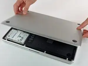
    • Slightly lift the lower case and push it toward the rear of the computer to free the mounting tabs.

    In the introduction you should link fixers to this excellent doc: https://www.ifixit.com/Misc/HD_Software_...

    It is really critical, super easy, and free(!) to clone your existing drive onto the new one you will install. I ran into one error, but SuperDuper! support replied immediately on how to fix it...Thanks ifixit and SuperDuper! (I ponied up the $28 for the software anyway, I was so impressed!)

    Mike -

    Long story short: I drank the AppleKoolAid back in 1984 and have always left the guts of my machines up to Apple - until recently when I needed to swap the SATAs from my original MacDaddy (2009 13" MBPro that I killed in 2018 - coffee + blackout = OOOOPS) into a pristine 2009 MBPro from a Goodwill in North Carolina through eBay. I need the files from iCal and MacMail that can't be opened in my newer machines.

    Well . . . I ain't never done nuttin' like that, before!

    Enter Luke Miani on YouTube. He raves about you guys! So, I watched everything I could, read your site, bought the right tools and at the ripe old age of 72, I sat down, this morning and did the work. Now my original MacDaddy lives in MacDaddy2.0.

    Am I allowed to cry?

    Seriously, I can't thank you enough for your bitchen site and killer tools. I wish I'd'a been turned on to this shizzle 30+ years ago.

    IFIXIT - IDIGIT!

    kath myers -

    HAHAHAHAHAHAHAHAHAHA.

    That was a brilliant read.

    Yes, I came across ifixit a few years ago. Totally helped me out on several occasions.

    Glad your Mac repair journey worked out.

    :)

    Cary B -

  3. B1SUXfcr5fruMavs
    • For precautionary purposes, we advise that you disconnect the battery connector from the logic board to avoid any electrical discharge.

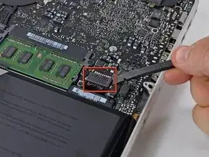
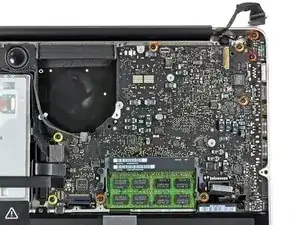
    • Use the flat end of a spudger to lift the battery connector up out of its socket on the logic board.

    Quote from gansodesoya:

    why is step 3 necessary?

    Just to disconnect any power source to avoid damages by short-circuits.

    MrKane -

    How do you get that battery connector back on? Do you just press it in back in place after you're done?

    Horace Chung -

    yes. I usually plug it in before I screw it down so I can lift the battery a bit and have enough slack to be able to go straight down on the connector, otherwise it comes in on a bit of an angle, which can't be good (though not necessarily bad).

    maccentric -

    This step almost finished me, and I did extensive damage to the battery plug. Fortunately, I later replaced the battery, and the replacement came with a new plug! :) Newbies need to know - 1. The battery plug is like a thin lip on a thicker lip, so you need to pry BETWEEN 2 thin lips to get it off, else you are trying to yank out the socket. 2. Mine was initially VERY tight, and trying to get it out broke the plastic on all sides of plug, even though I was as careful as possible. Luckily, this didn't hurt functionality and I later replaced the battery. AFTER disconnecting once, it was never so tight again,

    Jeff Diamond -

  4. kQ3R2wjKx61rvkCN
    kQ3R2wjKx61rvkCN
    cyUJCQ6xIrQCdlVw
    VXmuCnrn1lMbXlnb
    • Use a spudger to pry up the fan connector out of its socket on the logic board.

    • It is useful to twist the spudger axially from beneath the fan cable wires to release the connector.

    • The fan socket and the fan connector can be seen in the second and third pictures. Be careful not to break the plastic fan socket off the logic board as you use your spudger to lift the fan connector straight up and out of its socket. The layout of the logic board shown in the second picture may look slightly different than your machine but the fan socket is the same.

    The image is very misleading. This is why many people are breaking their connectors. Please correct this and make it VERY clear that one has to put the spudger straight behind the cables, NOT behind the connector, as shown in the pic.

    Giunia -

    Thankfully there is a helpful guide in the comments on this post for fixing the socket in the likely event that you snap the sucker clean off like I did:

    I popped off the fan connection from the logic board...Fix?

    agoodcourage -

    As Giunia said I too just broke the connector only because the photo shows to slide a spudger between the connector socket and the motherboard. I am now out of my only computer. This is VERY frustrating.

    Nha1234 -

    Broke it as well the picture is very misleading.

    Christian Flores -

    Local mobile repair shop soldered it back for me.. but it cost me twice as much as fan I ordered from china. They told me to use two tools in the future.. one to keep the edge down and other to gauge gently from under the cables...

    Bade -

  5. pFGTdZImDYtjO4b4
    • Remove the following three screws:

    • One 7 mm T6 Torx screw

    • Two 5.4 mm T6 Torx screws

  6. bbopIIjLSdISOvLS
    • Lift the fan out of the upper case.

  7. HMAf24Ge5JeKjrXC
    HMAf24Ge5JeKjrXC
    vcDy4UyFxXCqSMbd
    LoZj4jgRQpnOPEyA
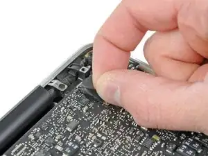
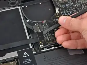
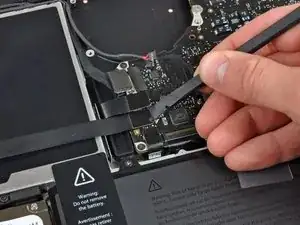
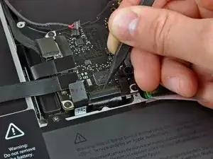
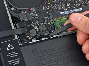
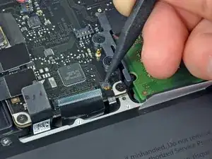
    • Grab the plastic pull tab secured to the display data cable lock and rotate it toward the DC-In side of the computer.

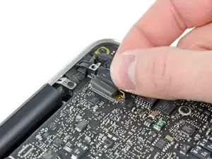
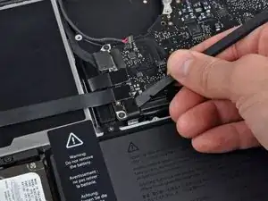
    • Gently pull the display data cable connector away parallel to the board.

    • Do not pull the connector upwards, or you may damage the connector.

    On my system the pad on top of the connector was shifted making the bracket difficult to rotate into the up position. The bracket looks like a handle so my first instinct was to pull it straight up. Big mistake. I ended up popping the brass guard off the connector on the logic board. The instructions could benefit from an arrow indicating the direction to pull and rotation of the bracket.

    highnoontoday -

  8. quIfTtoLygA1pOSJ
    quIfTtoLygA1pOSJ
    RUyjCQiOXECuiTPC
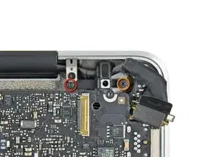
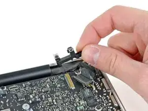
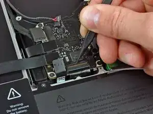
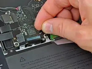
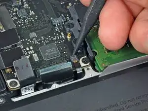
    • Remove the following two screws securing the display data cable bracket to the upper case:

    • One 8.6 mm Phillips

    • One 5.6 mm Phillips

    • Lift the display data cable bracket out of the upper case.

  9. 2pApI4moCDTnBuaR
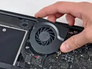
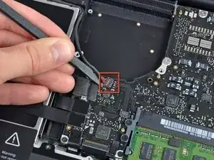
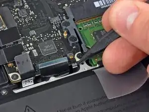
    • Use the flat end of a spudger to pry the subwoofer and right speaker connector up off the logic board.

    Push it straight down. It should snap in.

    BobG -

    The first time i tried this on a MBP 13 I broke the connector form the board. It should be noted that you have to be very careful in this step, as the plug fits very tightly and you can easily use too much force to tear the connector from the board. Use a second spudger to hold down the connector at its border and try very gently using a second spudger to move the plug out of the connector upwards.

    Joachim Kathmann -

  10. eT5TmcDL5Qy5VvaZ
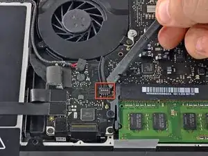
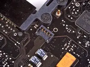
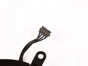
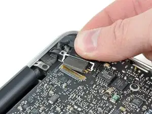
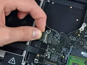
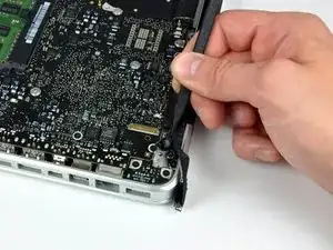
    • Pull the camera cable connector toward the optical drive to disconnect it from the logic board.

    • This socket is metal and can be easily bent. Be sure to align the connector with its socket on the logic board before mating the two pieces.

    As mentioned, the socket can be easily damaged when re-inserting it. I didn't care enough and one pin was damaged. Wifi was not detected.

    Hopefully the pin was not broken (only bent). Putting it back in its correct position, the wifi re-appeared.

    Arnaud ROSAY -

  11. wQtcOZqJFEcMuscb
    wQtcOZqJFEcMuscb
    MXnNM5NWNiSECMb2
    IKTPRlkXrAeF1BDD
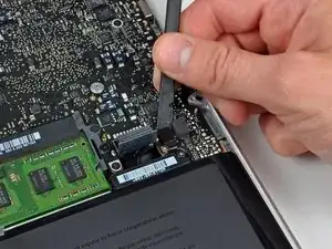
    • Use the flat end of a spudger to pry the optical drive, hard drive, and trackpad cable connectors up off the logic board.

  12. NCikjBxhaHd3CiRb
    NCikjBxhaHd3CiRb
    w1JBbMoOZJu6bgJD
    YyJRXXLQCKhgO3CP
    • Use your fingernail or the tip of a spudger to flip up the cable retaining flap on the ZIF socket for the keyboard ribbon cable.

    • Use your spudger to slide the keyboard ribbon cable out of its socket.

    Sometimes spulger is not the best tool to slide the cable out. If it is difficult to slide, try two toothpicks to pull the cable from two sides simultaneosly.

    Leo Nikitin -

    Toothpicks did the trick, thanks

    Gábor SEBESTYÉN -

    As Mateo said, replacing the zif cable is NOT easy, and in this case, will leave you with a computer that won't power on- this cable connects the power button. I learned a trick somewhere for dealing with these cables- put a piece of good sticky tape on the cable, and use it to pull it back into the connector. Works every time.

    stevesontheroad -

    Yeah! The tape trick worked for me. Thanks!

    Ted Bishop -

    Thank you Steve, it’s works perfectly.

    never_forever18 -

  13. xakWmCBC3OMuMyXe
    • Peel the small strip of black tape off the keyboard backlight ribbon cable socket.

    Be very careful while taking this black tape off. I accidentally broke the chip off the motherboard and so my keyboard is not backlit any more.

    Asim Akath -

  14. kMZTPOCecXPuvVLW
    kMZTPOCecXPuvVLW
    jJjWXgvVBQ1nhNR1
    qJl2UwjCZQndDIOF
    • Use the tip of a spudger to flip up the cable retaining flap on the ZIF socket for the keyboard backlight ribbon cable.

    • Use your spudger to slide the keyboard backlight ribbon cable out of its socket.

    Be especially careful as my hole socket detached from the board. It would have helped to vertically press the socket to the board with the tip of a spudger. Thus partially blocking the strap, you can first peel the free end, then change position and peel the rest. Slide the ribbon cable perfectly horizontally.

    Rainer -

    I had the same issue of trying to get the ZIF cable back in but found that if I used a piece of scotch tape, it worked. I followed this guide. MacBook unibody keyboard ribbon cable won't go in

    spearson -

    A reassembly trick that works for me is to use some 3/4" blue painters tape to stick to the very back (lower end) of the ribbon cable so I can pull it up and back before locking the cam. Trying to get a good grip without cutting, or crimping the ribbon means no tweezers or pliers can be used.

    originalmachead -

  15. GA4R6Z1udiBdAWjp
    • Use the flat end of a spudger to pry the battery indicator cable connector up off the logic board.

    If you’re swapping top cases, you might need to remove the battery indicator from the case and swap it to the replacement top case. It attaches with three very tiny Phillips screws. I wasn’t aware that my replacement top case didn’t have this part and got confused when reversing the steps to reassemble and I didn’t have this connector. I had to take the battery back out in order to swap the indicator over.

    Mark Barnes -

    Interesting this guide doesn’t have you disconnect the battery after step 2 then shows it unplugged already in step 14.

    plink53 -

    I would recommend revision to this guide to put battery disconnection as the first step after opening the bottom case. First rule of logic/mother boards: don’t work on or around if power is applied.

    dsfeehan -

  16. 5acPEhbAXlAZMqvR
    • Use the tip of a spudger to pry the microphone off the adhesive attaching it to the upper case.

    on the Australian/Asia version speaker cable is located underneath the logic board.

    linuxuser101 -

    Norwegian/European versjon too. Recommend using a pincer to lift it up.

    Note you’re not supposed to only remove the rubber, in fact that should stay on

    eisa01 -

  17. pUjsTWMyb1uXYtmK
    • Remove the following screws:

    • Two 7 mm T6 Torx screws from the DC-In board

    • Five 3.3 mm T6 Torx screws

    • Two 4 mm T6 Torx screws

  18. 1VTxI1RA5d52tAWU
    1VTxI1RA5d52tAWU
    WFrYefLTAEXc5BJN
    • Removing the battery before lifting out the logic board is not strictly required, but makes removing the logic board easier and safer. If you leave your battery in, be especially careful not to bend the logic board against the battery's case near its bar code.

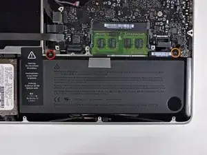
    • Remove the following Tri-point screws securing the battery to the upper case:

    • One 5.5 mm Tri-point screw

    • One 13.5 mm Tri-point screw

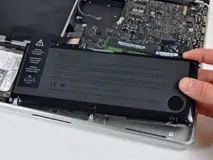
    • Lift the battery out of the upper case.

  19. dcGNaBIhDMgYwwJJ
    dcGNaBIhDMgYwwJJ
    2fc6NewMHSOyvrAg
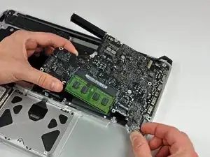
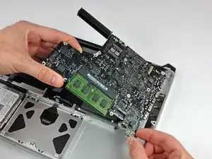
    • Lift the logic board from its left edge and raise it until the ports clear the side of the upper case.

    • Pull the logic board away from the side of the upper case and remove it, minding the DC-In board that may get caught.

    Be careful while taking the board out, as the heatsink usually is caught by the optic drive.

    Leo Nikitin -

    mid 2012: Careful of the left speaker (on your right because unit is upside down). Gently remove with spudger tool before removing logic board and when reinstalling press firmly back into place with spudger. Install speaker after putting logic board in place but before installing screws.

    JASON CULP -

    Step 18 is out of order. Steps following this show it still installed, which is confusing.

    plink53 -

  20. eVVN6ZnqVZuGdRG2
    eVVN6ZnqVZuGdRG2
    qk4ANAxrGTekpAlR
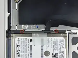
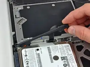
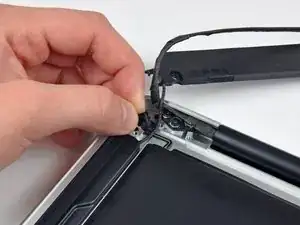
    • Remove two Phillips screws securing the hard drive bracket to the upper case.

    • The screws remain captive to the bracket.

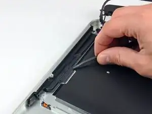
    • Lift the the retaining bracket out from the upper case.

  21. 3Wq65KUwV1361McL
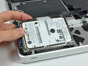
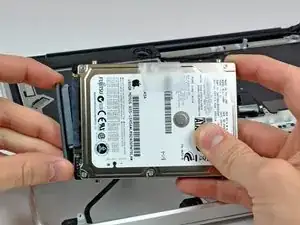
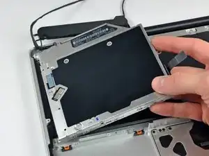
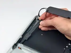
    • Lift the hard drive from its free edge and pull it out of the chassis, minding the cable attaching it to the computer.

  22. EHrGSDdk2OhRMtqD
    • Disconnect the hard drive by pulling the hard drive cable connector away from the drive.

  23. VDiIjdIHaQigcRlO
    VDiIjdIHaQigcRlO
    CLKgI23WlET4Ng1i
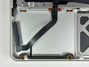
    • Remove the following four screws securing the hard drive and IR sensor cable to the upper case:

    • Two 1.5 mm Phillips screws.

    • Two 4 mm Phillips screws.

    • Slide the hard drive and IR sensor bracket away from the edge of the upper case.

    • Carefully peel the hard drive and IR sensor cable from the upper case.

    The orange-highlighted screws here are far longer than 4mm, aren't they?

    Shelley -

  24. wZkHxOXaqAZmwjMy
    wZkHxOXaqAZmwjMy
    bCVDvqV5cJ6klMID
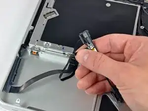
    • Remove the following screws securing the subwoofer to the upper case:

    • One 3.8 mm Phillips screw.

    • One 5 mm Phillips screw

    • The subwoofer is still connected to the right speaker, so don't completely remove it just yet.

    • Lift the subwoofer off the optical drive, and set it above the computer.

  25. qSXVxDBiYsy53IEn
    qSXVxDBiYsy53IEn
    a5cZn3ObepEHeVnO
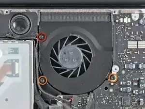
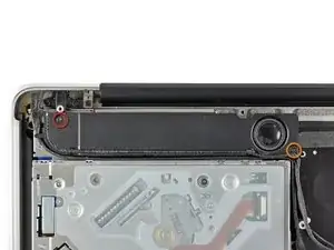
    • Remove the two 10 mm Phillips screws securing the camera cable bracket to the upper case.

    • The leftmost screw may remain captive in the camera cable.

    • Lift the camera cable bracket out of the upper case.

  26. n3XqLuRo4gUNcVDH
    n3XqLuRo4gUNcVDH
    JN1a4xaIyeIZJKvG
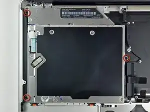
    • Remove the three 2.5 mm Phillips screws securing the optical drive to the upper case.

    • Lift the optical drive from its right edge and pull it out of the computer.

  27. bPwfvIZjVRbhZ2bF
    • Peel back the small piece of black tape covering the right speaker cable.

    • Be careful, as the power button ribbon cable is directly under this piece of tape.

  28. RrW2V2VjdXTNw2EA
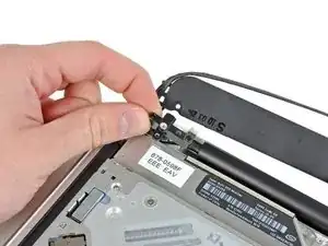
    • Use the tip of a spudger to pry the right speaker up off the adhesive securing it to the upper case.

    I found it easiest to start at the bottom (hard drive side) of the speaker.

    Michael Vovaris -

  29. rWxdYHWu5DAqPHfR
    • Lift the subwoofer and right speaker assembly out of the upper case.

  30. LJk6WPEmLOKPqLya
    LJk6WPEmLOKPqLya
    tiRqyU1XgWd6dAwt
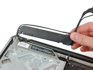
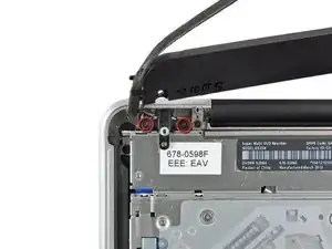
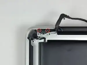
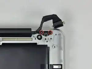
    • Remove the two outer T8 Torx screws securing each side of the display bracket to the upper case (4 screws total).

  31. ys5jHYc3kMAycZYN
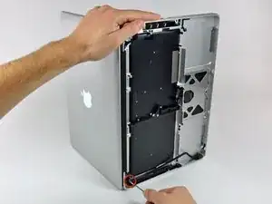
    • Open your MacBook so the display is perpendicular to the upper case.

    • Place your opened MacBook on a table as pictured.

    • While holding the display and upper case together with your left hand, remove the T8 Torx screw from the lower display bracket.

  32. cKR4jTENjthgiuoc
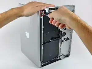
    • Be sure to hold the display and upper case together with your left hand. Failure to do so may cause the freed display/upper case to fall, potentially damaging each component.

    • Remove the last remaining T8 Torx screw securing the display to the upper case.

  33. Omg4geDHqqTOW1PD
    Omg4geDHqqTOW1PD
    UaYb1tJCdopbtR4L
    3JdXYUE51TghN4KN
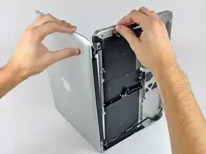
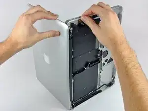
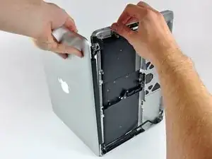
    • Grab the upper case with your right hand and rotate it slightly toward the top of the display so the upper display bracket clears the edge of the upper case.

    • Rotate the display slightly away from the upper case.

    • Lift the display up and away from the upper case, minding any brackets or cables that may get caught.

Conclusion

To reassemble your device, follow these instructions in reverse order.

Walter Galan

694047 Reputation

0 comments