Introduction

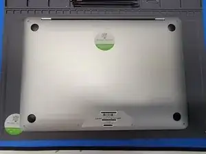
Use this guide to replace a touchbar on an A2289 Macbook Pro 13" Mid 2020.

Be mindful to keep all screws and brackets organized. This will keep from damaging sensitive components by accidently screwing the wrong size screw in.

  1. p5mR4CqYXVDKULTm
    p5mR4CqYXVDKULTm
    JIBRB6ZguRTSPouH
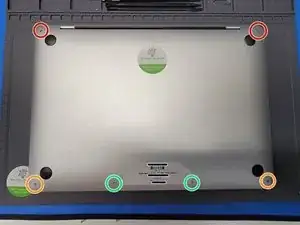
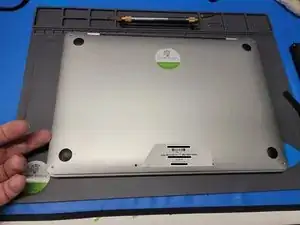
    • To begin, we will need to remove 6 total screws

    • 2x 6.9mm Pentalobe P5

    • 2x 5.5mm Pentalobe P5

    • 2x 3.5mm Pentalobe P5

  2. fnIXlq1PD16FrpcN
    fnIXlq1PD16FrpcN
    gIWJmBPSBOWIVhWP
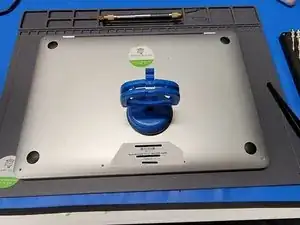
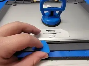
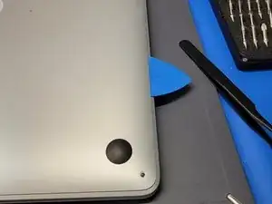
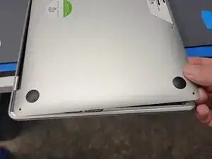
    • After the screws are removed, grab a suction cup. We used iFixit's Heavy Duty Suction cup.

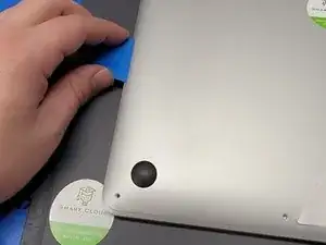
    • Place the suction cup towards the bottom of the Macbook

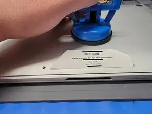
    • Pull up on the suction cup; Creating about 0.15in worth of space from the panel and the Macbook.

    • Don't lift it any higher, as it could damage inside compenents

  3. GbMiPLvtdwcWIagq
    GbMiPLvtdwcWIagq
    KgM1ZZhiTK3AOBHp
    EyEVtl5DkyHRYnuV
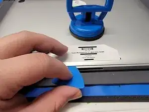
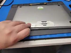
    • While creating the gap between the Macbook and the back panel, insert an opening pick into the gap about 0.2in.

    • Don't insert the pick further, as this could cause internal damage

    • Move the pick towards the left side of the Macbook and around the corner edge.

    • Bring the pick up towards the top of the Macbook

    • Once you reach about the middle of the Macbook, you should hear a click. This is good! You have now unhooked part of the back panel.

  4. CLFWunEgOGMJkevG
    CLFWunEgOGMJkevG
    IBDfi4ZE2bKIKd1A
    • Repeat Step 3 but on the right side of the Macbook

    • Once done, don't remove the back panel just yet. It is still attached to the Macbook

  5. TJmOigsMFjRkaEGm
    TJmOigsMFjRkaEGm
    TISivDrNh4oeeapM
    • Insert your fingers in-between the back panel and Macbook and pry upwards to unhook the middle hook keeping the back panel connected to the Macbook

    • Don't attempt to remove the back panel yet. It is still connected to the Macbook

  6. STIPEZnwI4wIe3aO
    STIPEZnwI4wIe3aO
    iKqbeKKsEqNJCHcR
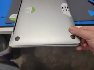
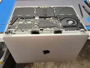
    • Grip the back panel with one hand

    • Grip the Macbook with the other hand

    • And pull the left side of the back panel AWAY from the HINGE side of the Macbook

    • This will require a lot of force. Don't be afraid to pull hard while keeping the Macbook steady and in position.

    • Repeat this with the right side of the Macbook

    • Once pulled from the hinge area, you may now remove the back panel and place it out of the way.

  7. BSWhuvJJrcXBPWb5
    BSWhuvJJrcXBPWb5
    d1NtuSyofxVZaNYn
    t5Pr4W3WPKffOLAg
    • Locate the battery connector cover

    • Take a pair of tweezers and gently remove the plastic cover from the Logic Board

    • Be careful not to pull on any flex cables

  8. DJMxKg5HPyTLC5WU
    DJMxKg5HPyTLC5WU
    RRhblJqCBcSJWWON
    RPV2EgbODqqsFqt2
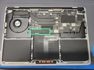
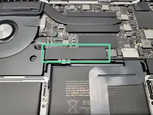
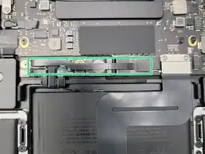
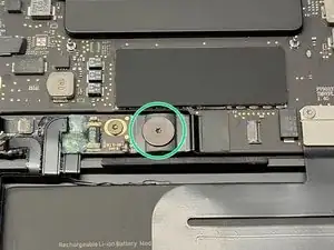
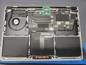
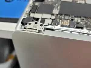
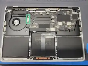
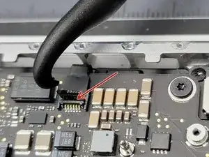
    • Locate the small flex cable covering the battery terminal

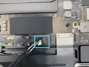
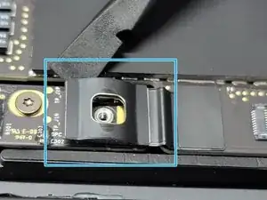
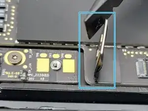
    • Take a pair of tweezers in one hand and pull up on the plastic flap

    • Take the hook end of a Halberd Spudger in the other hand and gently pry up the retaining flap on the battery cable ZIF socket

    • Be sure you are prying up on the hinged retaining flap, not the socket itself.

    • Make sure to use gentle force as this shouldn't require a lot of force. If excessive force is used, you could break the flex cable.

  9. 1NkdDkolQXyX2bt5
    • Take your tweezers and pull on the plastic cover away from the ZIF socket to remove the flex cable from it's socket

    • Make sure to use gentle force as this shouldn't require a lot of force. If excessive force is used, you could break the flex cable.

  10. G5vIVteKGuBThADJ
    G5vIVteKGuBThADJ
    CLStXvZgIVEY6dhZ
    ysv5qgDBIiB3yBHq
    • Remove the 3.8mm Torx T5 screw from the battery connector

    • Take the flat end of a spudger and pry up the battery connector to a 90° angle

    • Prying it this far away from the contact pads ensures there won't be any contact between the Logic Board and the battery

    • Be mindful of the battery connector. If you flip the Macbook and lay it down on the table, you could damage the battery connector

  11. Ct3ZvKEiNAjLs3Yk
    Ct3ZvKEiNAjLs3Yk
    3oIB1XOPSqCvJR3h
    2PYX2PxjvGSAMZGT
    • Locate the left hinge cover

    • Remove 2x 2mm Torx T3 screws securing the hinge cover to the Macbook

    • Take a pair of tweezers and remove the hinge cover

  12. 2RQjKyImBDwOw2Aq
    2RQjKyImBDwOw2Aq
    mCVIEmai3oLtSM1b
    o3kXKGlKyRP1idMA
    • Locate the right hinge cover

    • Remove 2x 2mm Torx T3 screws securing the hinge cover to the Macbook

    • Take a pair of tweezers and remove the hinge cover

  13. 2LDMbUsoyTinlIhA
    2LDMbUsoyTinlIhA
    Su2RUyWNGRSwAZOS
    YryUtiHDGcNwLicp
    • Locate your LCD flex cable towards the top of the Macbook

    • Locate the bottom cover plate

    • Remove 2x 3.2mm Torx T3 screws securing the bottom cover plate to the MacBook

    • Take a pair of tweezers and remove the brackets

  14. xQtTh1JTjJJlBTGU
    xQtTh1JTjJJlBTGU
    V2O1yy4DueTJbXNF
    • Locate the top cover plate of the LCD flex cable

    • Remove 2x 1.8mm Torx T3 screws securing the top cover plate to the Macbook

    • Take a pair of tweezers and remove the now free cover plate

  15. cAFfkUXVM6Cq5HEG
    cAFfkUXVM6Cq5HEG
    2ITiRMHExVB1i3Mm
    PeRTpXAnKF1fpcKN
    • Take the flat end of a spudger and gently pry up the LCD flex cable from its port

    • Make sure not to pry the socket itself

    • Lift LCD flex cable up and away from the Macbook

  16. omGVnPUfkkxJHBbI
    omGVnPUfkkxJHBbI
    Hpb21E3JNacJGUVQ
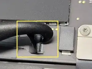
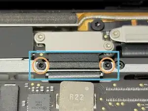
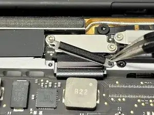
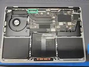
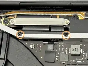
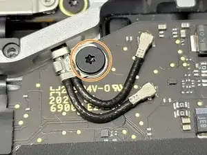
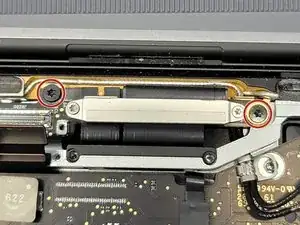
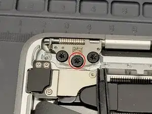
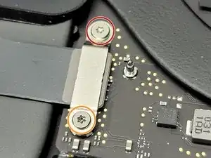
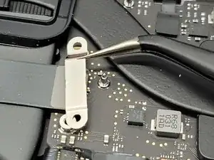
    • Locate the left LCD screen spring

    • Remove 2x 4.1mm Torx T3 screws securing the spring to the MacBook

  17. 5Sk1goE6xnfBLcBh
    5Sk1goE6xnfBLcBh
    EXi1mVgIbDP3Yi2J
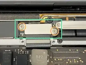
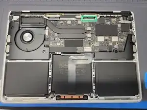
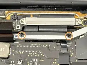
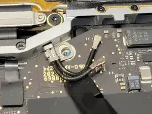
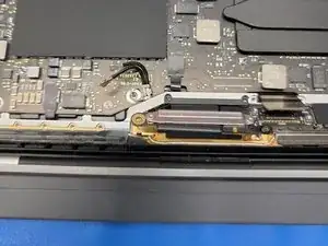
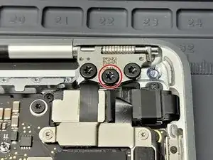
    • Locate the right LCD screen spring

    • Remove 2x 4.1mm Torx T3 screws securing the spring to the MacBook

  18. JbCdsqIdsSgHqbKO
    JbCdsqIdsSgHqbKO
    hSKhbSSlwdgPwxCd
    PAXOiFtNy4fa4ZwP
    • Locate antenna connector cover

    • Take a pair of tweezers and gently pry up the cover from the Logic Board

    • Be careful not to pry anything but the plastic cover

    • Remove 1x 3.9mm Torx T5 screw securing the antenna cables to the MacBook

    • Take the flat end of a spudger and gently pry up the antenna cables from their sockets

    • Be careful not to pry up the socket itself

  19. 42qsBrXMXMfDCN13
    42qsBrXMXMfDCN13
    rNG5pC1WyvKTdffX
    s6WXBLvseSLbkGjr
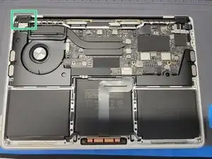
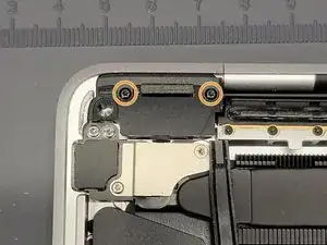
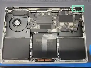
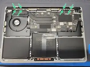
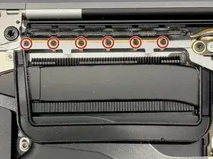
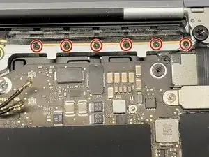
    • Locate the antenna towards the top of the Macbook

    • Remove 12x 1.2mm Pentalobe P2 screws securing the antenna to the MacBook

  20. Q4sZtGgPaymKZHof
    Q4sZtGgPaymKZHof
    MBpUZYdZ23gf1SEu
    cmLfUuOfXmUG3BbO
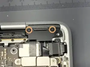
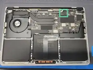
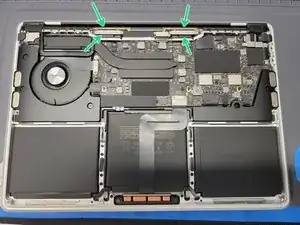
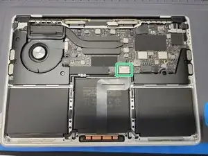
    • Locate the LCD board towards the top of the Macbook

    • Remove 4x 3.4mm Torx T5 screws securing the LCD board to the MacBook and to the antenna

  21. QQLsp1eqYxuyQTwQ
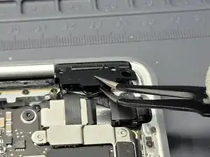
    • You should now be able to remove the antenna from the Macbook.

    • Gently pry & pull away the antenna cable from the Macbook while routing it's cable through their hole. Take care here, as the antenna sockets can be ripped from the board easily.

    • You can straighten out the cables to make it easier or simply twist and turn the antenna to maneuver the cables out of their hole.

  22. Xm2SWRZOqZpdkPKI
    Xm2SWRZOqZpdkPKI
    EOnNxhBvSfVUSPvK
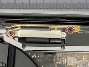
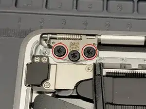
    • Locate the left LCD screen hinge

    • Remove 2x 4.5mm Torx T9 screws that secure the hinge to the MacBook

    • Leave 1 screw to make removing the LCD screen easier

  23. AKBDGGbdDyWYhvSM
    AKBDGGbdDyWYhvSM
    CQLChUUqfoITLDRp
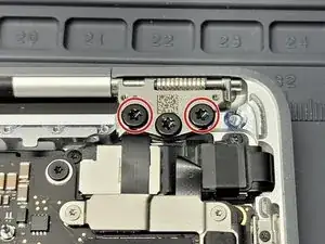
    • Locate the right LCD screen hinge

    • Remove 2x 4.5mm Torx T9 screws that secure the hinge to the MacBook

    • Leave 1 screw to make removing the LCD screen easier

  24. QyDRGlywk2ivcGrH
    QyDRGlywk2ivcGrH
    3smtqKa6NteA5jKk
    eWb3ULCZEMYddQNZ
    • Place MacBook at the edge of your work bench and let the screen overhang

    • Locate and remove the remaining 2x 4.5mm Torx T9 screws securing the 2 hinges to the MacBook

    • The MacBook display will now freely dangle on the edge of the table. It won't fall due to the hinges being inside a divot in the MacBook

  25. ipTfLVDSydqOsUOC
    ipTfLVDSydqOsUOC
    Q4b5jOwUYIcMcXRd
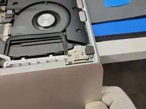
    • Bend the LCD screen slightly towards you

    • Gently pry up the LCD screen from the Macbook, while guiding the hinges out of their divots

    • During reassembly make sure to place the hinges into the divots. Once in the divots, you can then screw 1 screw back into each hinge and then shut the Macbook. This will allow you to properly arrange and align the LCD hinges

  26. Ke1ADnrbLCBW3EI4
    Ke1ADnrbLCBW3EI4
    BwCEMdIBOTysHUQM
    jZn3M4qiYECYLQiU
    • Locate the power button flex cable bracket towards the top left of the MacBook

    • Remove 2x screws securing the bracket to the MacBook

    • 1x 5mm Torx T3 Screw

    • 1x 1.4mm Torx T3 Screw

    • During Reassembly: You may want to use this screw to screw in the logicboard standoff underneath.

    • Take a pair of tweezers and remove the bracket

    • Make sure to grab and pickup ONLY the bracket.

  27. WvwaTYsm4UH6TUNG
    WvwaTYsm4UH6TUNG
    Oxh5Cduqkbmx35mh
    1TraBZSWOHYPY3nv
    • Locate the trackpad's flex cable bracket towards the middle of the Macbook

    • Remove 2x 1.9mm Torx T5 screws securing the bracket to the Macbook

    • Then take a pair of tweezers and remove the bracket

    • Make sure to grab and pickup ONLY the bracket.

  28. k32KyG6C2lITKCtN
    k32KyG6C2lITKCtN
    iAEUuC5Q2cONwJW2
    lYALXKcdROkQmL1y
    • Using the flat end of a spudger gently lift the connector from its socket

    • Make sure to not pry the socket itself

    • It might make it easier if you pry it up a little on all 3 sides

  29. dvwXpfbyNaFCJVXO
    dvwXpfbyNaFCJVXO
    oxVQGYInPGREAcW6
    GRlcCyePHyL6fuTe
    • Locate the right speaker flex cable bracket

    • Remove 2x screws securing the bracket down to the Logic Board

    • 1x 3.7mm Torx T5

    • 1x 2.6mm Torx T5

    • Take a pair of tweezers and remove the bracket

    • Make sure to not grab the flex cable while removing the bracket

  30. AMQDBFvYLXo35pac
    AMQDBFvYLXo35pac
    ZtFTLwsxAACsln3F
    • Take the flat end of a spudger and carefully pry up the flex cable from its socket

    • Be careful not to pry up on the socket itself

    • There are sensitive filters near the socket. Make sure to be ultra careful not to knock one of those "microscopic" filters off.

  31. BaVQFechroYZ1c1K
    BaVQFechroYZ1c1K
    IMcGUkyY1cHVOKPA
    PVf1HKeom2tuYZ2C
    • Locate the left speaker and touch bar bracket

    • Remove 3x 1.4mm Torx T3 screws from the bracket

    • Take a pair of tweezers and remove the bracket

    • Be sure not to grab any of the flex cables while removing the bracket

  32. 4RwmCCSoEHMhtWiS
    4RwmCCSoEHMhtWiS
    PAErWdlNONTaoKaK
    Itrew1gKDDGrIx6g
    • Take the flat-end of a spudger and gently pry up all 3 flex cables from their sockets

    • Be careful not to pry up on the socket itself

    • There are sensitive filters near the socket. Make sure to be ultra careful not to knock one of those "microscopic" filters off.

  33. Y3YQ6AybC1iQDPp3
    Y3YQ6AybC1iQDPp3
    EfEdJN1orSrt54SZ
    ASSm3ajWFqwPMnNx
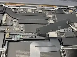
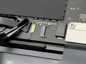
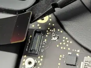
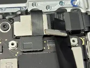
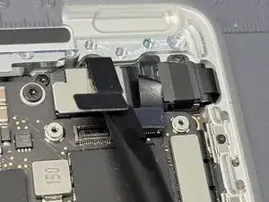
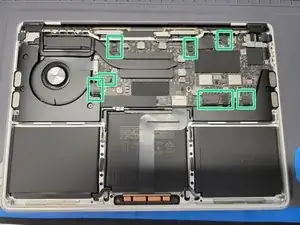
    • Locate 8x flex cables connected the logic board

    • For each flex cable, pull up on their plastic flap with a pair of tweezers

    • Take the hook end of a Halberd Spudger and gently pry up the retaining flap on the ZIF socket of each cable

    • Make sure to use gentle force as this shouldn't require a lot of force. If excessive force is used, you could break the flex cable.

    • Be sure you are prying up on the hinged retaining flap, not the socket itself.

    • Take your tweezers and pull on the plastic cover to pull each cable away from the ZIF socket to remove the flex cable from it's socket

    • Make sure to use gentle force as this shouldn't require a lot of force. If excessive force is used, you could break the flex cable.

    • If any of the plastic flaps break off don't worry! You can use a combination of your spudger and tweezers to gently pull out the flex cable from it's respective socket

  34. 6eCO5s4emDcxBdwn
    6eCO5s4emDcxBdwn
    uTacegkjAkdhgnc3
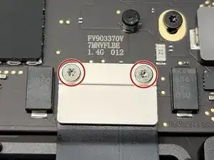
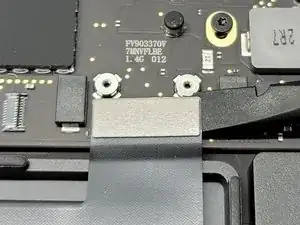
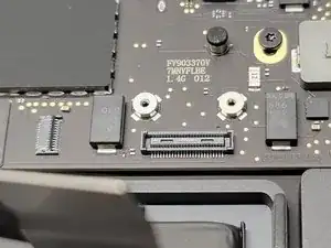
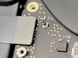
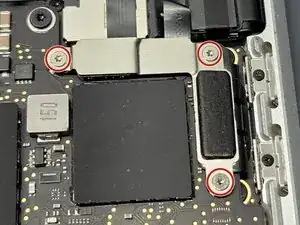
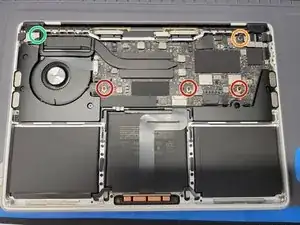
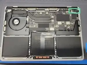
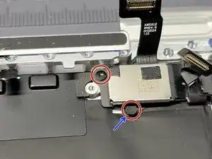
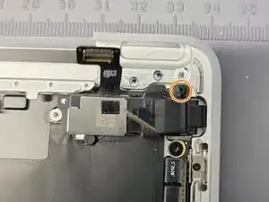
    • Locate and remove 5x Logic Board Screws

    • 3x 3.4mm Torx T5 screws

    • 1x 3.6mm Torx T5 stepped screw

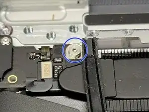
    • 1x 3.3mm hex standoff (3mm drive)

    • During Reassembly: It may be difficult to screw the top left logic board standoff back in. If you are finding it hard to do this, take the 1.4mm screw that we removed to remove the power button bracket and screw it into the top left logic board standoff. Afterwards, take the now "cyborg" screw and screw it into the logic board.

    • Don't forget to remove the 1.4mm screw from the logic board standoff during reassembly

  35. S2qBe12iP1ChKocI
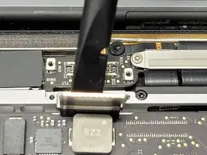
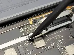
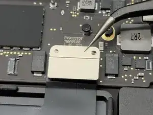
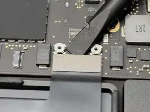
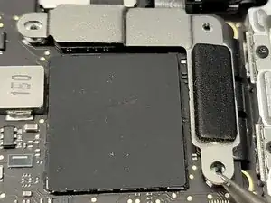
    • Take the hook end of your Halberd Spudger and gently pry up the top left corner of the logic board

    • Now remove the logic board from the Macbook

    • Be careful not to rip or tear any flex cables while removing or placing down the logic board

    • During reassembly, make sure to take your spudger while placing the logic board down and move any flex cable away from being squashed, tore, or ripped.

  36. 21HNZVksBKKCQmq5
    21HNZVksBKKCQmq5
    H5SZtXn3BXVUPpIE
    JUP2MjO2HkMqbMIG
    • Locate the touchbar flex cable mess towards the top right of the Macbook

    • You will be removing a total of 3 screws to release this cabled mess from the frame

    • 2x 2.4mm

    • One of these are "hidden" by a small pad. Take a pair of tweezers and remove this pad to access the screw head

    • 1x 1.7mm

    To complete this excellent guide: Use T3 screwdriver.

    Claus Pfisterer -

  37. FnDfwuCItyG2QMeE
    FnDfwuCItyG2QMeE
    R2sYWE1iFkwSIkGE
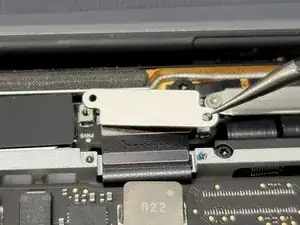
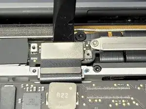
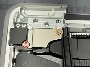
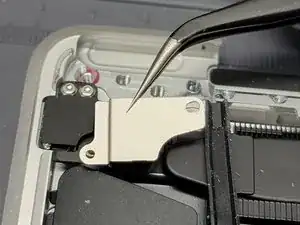
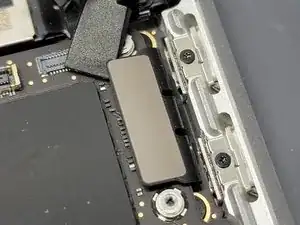
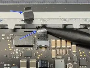
    • These brackets that keep the cabled mess down and attached to the frame are adhered to the cabling

    • Remove these brackets from the flex cabling mess

    • TIP: Be mindful of how the brackets are positioned in relation to the cables and frame. Take pictures to reference. Without these brackets, the cables will be free inside the frame (which is not good).

    • There are also little wraps of plastic holding different parts of the cabling together. Go ahead and CAREFULLY remove these as we won't need them during reassembly and we do need them removed to completely remove the touchbar

    • Follow this guide to properly install the new touchbar

  38. qSTaOj2K1OCBGY5O
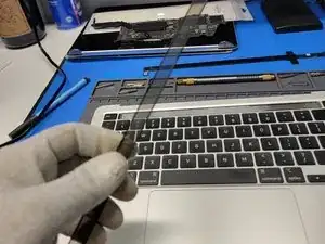
    • There are 2 methods that we can take towards removing this annoying touchbar. We went ahead and performed what we thing is the harder method.

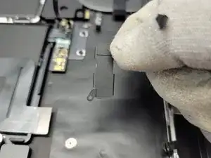
    • Method 1: Take 2 tweezers or handles and wrap very thin wire around them. Then pull the wire underneath the touchbar LCD gently while being careful not to damage the keyboard

    • This method keeps the frame underneath the touchbar from scratching a whole bunch, eliminates the possibility of the keyboard keys "melting" from the Adhesive Remover, and allows you to possibly reuse the touchbar.

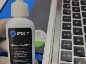
    • Method 2: What we did. Remove the touchbar digitizer first by prying it up and off the touchbar LCD. Then use a combination Adhesive Remover and a Technician's Razor Set to remove the touchbar LCD.

    • This method takes longer and more patience. However, we didn't have wire at our disposal and we weren't needing to reuse the touchbar

  39. byBqRQJVncxRR522
    byBqRQJVncxRR522
    RohtZjSfZkmrXqXC
    EUBGBTuj6EZCu16w
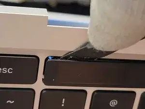
    • Take a Halberd Spudger and insert the knife end right underneath the plastic of the digitizer

    • Run the Halberd Spudger along the edge of the touchbar digitizer

    • The digitizer should separate surprisingly easy.

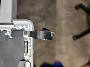
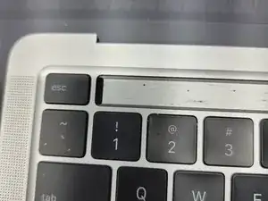
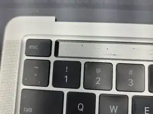
    • Feed the Touchbar digitizer cable through the hole and remove the digitizer

  40. YdZu5aNk42HNNEBK
    YdZu5aNk42HNNEBK
    B1DKmLsGOFvDHQVy
    • Take a technician's knife and start prying away the LCD of the touchbar.

    • Use adhesive remover from time to time to help loosen the adhesive

    • Don't let any of the adhesive remover touch the keyboard keys or any plastic for that matter. It will melt and eat away at any plastic it comes in-contact with

Conclusion

To reassemble your device, follow these instructions in reverse order. Follow this guide to reinstall the new touchbar properly.

We here at Smart Cloud hope your project goes smoothly and without a hitch. However, things happen and we want to make sure you know we are here to help if needed. You may contact us if needed as we can provide support or repair options per request. Good luck and have fun.

Thomas Kirschbaum

Member since: 27/03/20

1711 Reputation

3 comments

Bonjour, excellent tuto. Bien réalisé grâce aux outils MAKO de ifixit.

Etape 31, il faut utiliser T5. Les 3 vis n'ont pas toutes la même longueur.

J'ai cassé un connecteur sur la carte : est ce que je peux mettre de la colle chaude pour tenir la nappe ?

Encore merci pour cette précieuse aide

Nize -

Hello, What is the connector of the photo 20210430_142817.jpg? I broke it :-((. Since the reassembly, the microphone and the backlight of the keyboard do not work : how to fix them? in advance thank you for your help - Best regards Nize

Nize -

This guide saved the data on a 2020 M1 MacBook Pro 2hrs after falling into a bathtub. Thank you!

MotorMac -