Introduction

Prereq to remove the logic board

  1. vWZyGPJjlhcyPBEA
    vWZyGPJjlhcyPBEA
    6Gf4pvuNTLrfsLTh
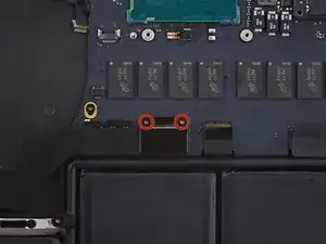
    • Remove the two 2.1 mm T5 Torx screws securing the I/O board cable bracket to the logic board.

    • Remove the I/O board cable bracket.

  2. IABfnvG4AyfPANkb
    IABfnvG4AyfPANkb
    TEtyEJ5wVoesOAPs
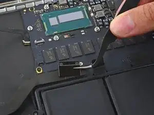
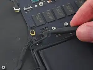
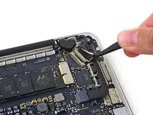
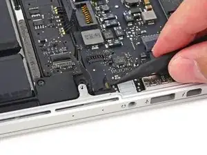
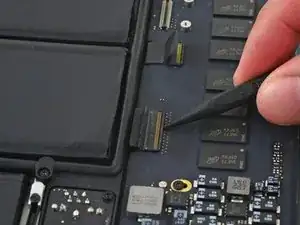
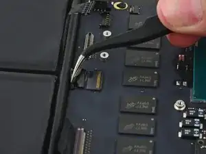
    • Use the flat end of a spudger to pop the I/O board connector straight up off its socket on the logic board.

    • Be careful to only pry up on the I/O board cable, not on the socket itself or you risk damaging your logic board.

  3. EenMPiRLiARjwEEW
    EenMPiRLiARjwEEW
    BS4xBgUQxoxPTMxo
    • Lift the logic board end of the I/O board cable straight up to bend it out of the way.

    • To avoid damage to the cable, fold only at the bend in the I/O board end of the cable.

  4. vAUEPShEOq4TA2AR
    vAUEPShEOq4TA2AR
    GIuW4iY4hvQZ3FuI
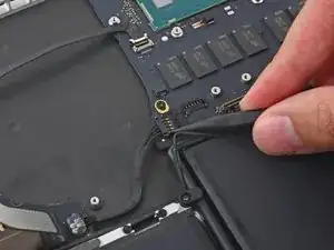
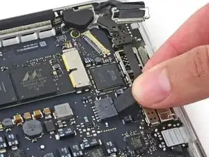
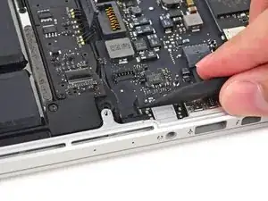
    • Use the tip of a spudger to lift the right speaker connector straight up out of its socket on the logic board.

  5. 2Rr5m1cecBMSExrM
    2Rr5m1cecBMSExrM
    NDcEFVLGwmrx2fjP
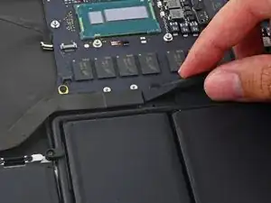
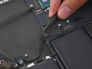
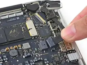
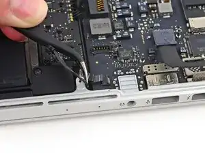
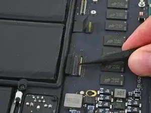
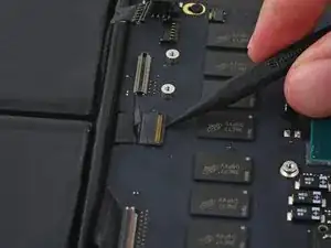
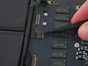
    • With the tip of a spudger, push on either side of the I/O board connector to walk it out of its socket on the logic board.

    Having a hard time at this step. Any suggestions? it's just not walking out.

    Moki -

    Use your fingernails to pinch the sides of the clip inwards to release the connector. I couldn’t walk it out either, both sides needed to be pushed in simultaneously to pull it out of the socket.

    maccentric -

    Do not pull from the cables end. you will risk separating thin cables from connector head. Use spudger tip to push it out.

    Macrepair SF -

  6. pI6fcBR1WwNQJq1f
    pI6fcBR1WwNQJq1f
    NJmNXhItOnrJMy3C
    LMg4wkugObTV2Pqm
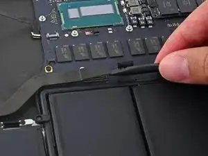
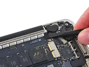
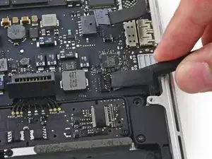
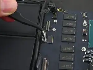
    • Use the flat end of a spudger to disconnect the keyboard backlight cable and bend it up out of the way of the logic board.

  7. iENKDDRt1Kiq5O5M
    iENKDDRt1Kiq5O5M
    BIVWpJDXtifJE4hC
    gISc6J22ma2o5UZK
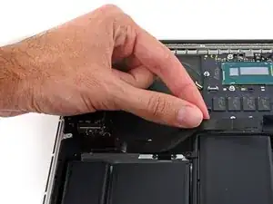
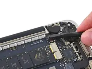
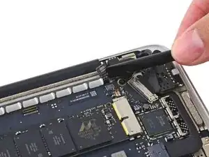
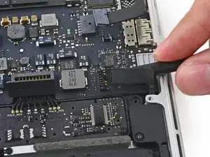
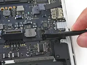
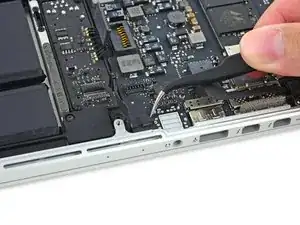
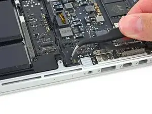
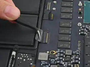
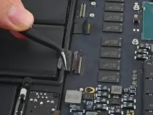
    • Grab the black plastic tab to flip the display cable connector open and pull it straight out of its socket on the logic board.

  8. IOHJOH1cFJHypoBV
    IOHJOH1cFJHypoBV
    saRcGXe4SitRnh1h
    • Carefully pull the DC-In board connector straight out of its socket on the logic board.

  9. rnUMTOatBJNNgBni
    rnUMTOatBJNNgBni
    jOSJGYDNOwqKXKTJ
    UXwgmKPKT4ZdQxwZ
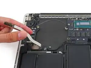
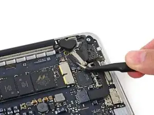
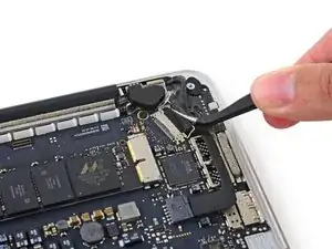
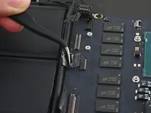
    • Wedge the flat end of a spudger under the left speaker cable near the connector and lift it straight up out of its socket and fold it out of the way.

  10. LHnsgIhIncp5eheR
    LHnsgIhIncp5eheR
    NF4gbNSjjH2orU1b
    • If necessary, peel back any tape covering the microphone cable ZIF connector.

  11. ovyqUQhyDW2jNSUR
    ovyqUQhyDW2jNSUR
    v5WS3ylaa6lZA3Na
    5JY4d3RdORBCkYdv
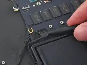
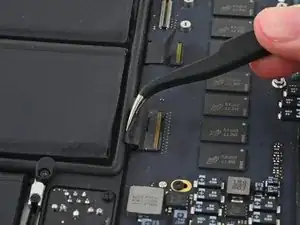
    • Use the tip of a spudger to flip the retaining tab on the microphone cable ZIF connector.

    • Pull the microphone cable out of its socket on the logic board.

  12. DwllTxgbmkLCheAb
    DwllTxgbmkLCheAb
    WaEQ5WQEHDKoMg53
    65XSFpLW1UjClqPx
    • If necessary, peel back any tape covering the keyboard cable connector.

    • Use the tip of a spudger to flip the retaining tab on the ZIF connector.

  13. UYrMGfTxWPjSP2iO
    UYrMGfTxWPjSP2iO
    DCC3ttZgUYA32Mkn
    • Pull the keyboard cable straight out of its ZIF socket on the logic board.

  14. ySdRCDWqGVypWNvp
    ySdRCDWqGVypWNvp
    gxvAprDPTjBvHvOr
    TvnBUIBNlrlJEXoa
    • If necessary, peel back any tape covering the trackpad cable connector.

    • Use the tip of a spudger to flip the retaining tab on the ZIF connector.

  15. OPwvQ3O253Far5tX
    OPwvQ3O253Far5tX
    NxHcUYBWvMoJFjcZ
    • Pull the trackpad ribbon cable straight out of its socket on the logic board.

    I didn’t pay enough attention when I pulled the ribbon cable out, so trying to figure out how to reattach it was quite challenging for me. After searching unsuccessfully for videos/instructions on how to reattach, I finally figured out that the ribbon cable goes UNDER the black plastic part of the socket (closest to the ribbon), and then you push the little tab down to hold it in place. Hope this helps others who are struggling with this part. Otherwise, this was an amazing tutorial, and saved my macbook…

    CRI -

  16. jIDstOHgGrwoCs1E
    • Remove the five 3.5 mm T5 Torx screws securing the logic board to the upper case.

    • When reassembling, install all five screws loosely, position the logic board, and then tighten evenly.

  17. mYJ2dVthDJKvyRJi
    mYJ2dVthDJKvyRJi
    f6brs14Ux1JKCBiR
    2AgvhQLwAy2Ik5bI
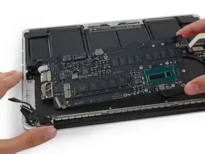
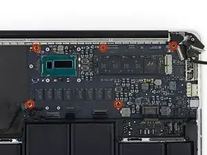
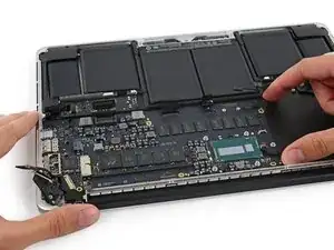
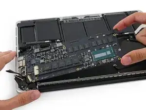
    • Lift the processor end of the logic board up slightly and pull it toward the fan recess to free the ports from the edge of the upper case.

    • Remove the logic board.

    • When reinstalling, make sure the keyboard, keyboard backlight, MagSafe, and microphone cables don't get trapped beneath the logic board.

    • Also be sure to slide the ports' metal EMI fingers under the side of the case, not over.

Conclusion

To reassemble your device, follow these instructions in reverse order.

Sam Goldheart

Member since: 19/10/12

465332 Reputation

One comment

Thanks for the the instructions. I have a question that I couldn’t find on the answers forums. Is there any thermal paste or just general cooling system considerations when replacing the logic board?

Brad Bowman -