Tools
Parts
-
-
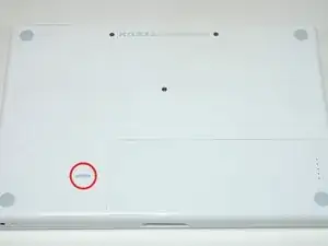
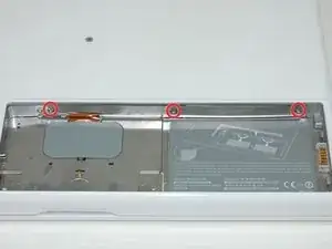
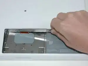
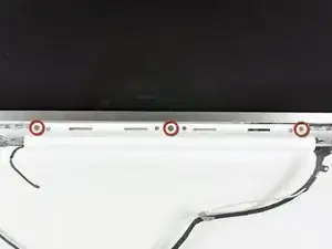
Remove the three evenly-spaced Phillips screws from along the rear wall of the battery compartment.
-
-
-
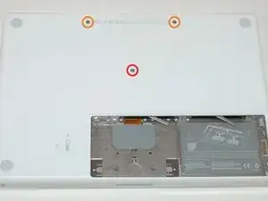
Remove the following 3 screws:
-
One 11 mm Phillips #00 in the middle of the case.
-
Two 14.5 mm Phillips #00.
-
-
-
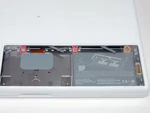
Remove the following 3 screws from the rear wall of the battery compartment:
-
Two 3 mm Phillips #00. (A1181 has three 3 mm screws and one 4 mm.)
-
One 4 mm Phillips #00 on the right side.
-
-
-
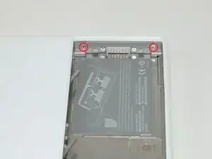
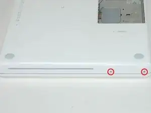
Remove the two 6 mm Phillips #00 screws from either side of the right wall of the battery compartment (not the ones closest to the battery connector).
-
-
-
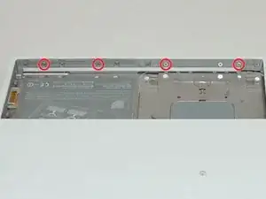
Remove the four 3 mm indicated Phillips #00 screws from the front wall of the battery compartment. When working from the left, remove the 2nd, 4th, 7th and 9th screw.
-
-
-
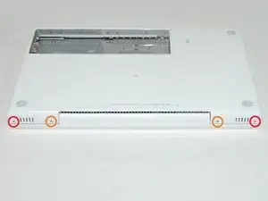
Remove the following 4 screws from the back of the computer:
-
Two 7 mm shouldered Phillips on the far sides.
-
Two 10.5 mm Phillips toward the center.
-
-
-
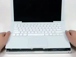
Starting near the display and working around to the front of the computer, pry up on the upper case. It is held with clips on the right above the optical drive. These will release with some firm lifting pressure.
-
Be careful when prying up the upper case. It's very easy to slice open a fingertip and thus provide the blood sacrifice the Mac gods sometimes require of those who insist on doing their own repairs.
-
-
-
While holding up the upper case (from the bottom or the top), use a spudger to pry up the orange trackpad and keyboard cable from its connector.
-
-
-
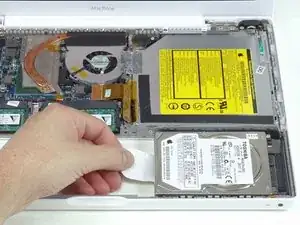
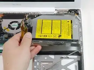
Grasp the white plastic tab attached to the hard drive and pull it to the left, removing the hard drive from the computer.
-
-
-
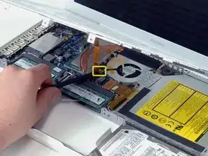
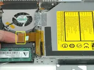
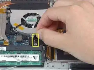
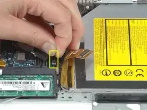
Disconnect the newly-revealed display data cable. If there is no pull-tab on the top of the connector, it may be helpful to use a spudger to disconnect this connector.
-
-
-
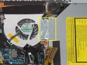
Peel up the foil tape between the fan and the optical drive.
-
Remove the 8.5 mm Phillips screw securing the display data cable to the metal framework.
-
-
-
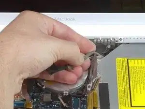
Pull up the display data cable from along the edge of the optical drive to reveal a silver Phillips screw.
-
-
-
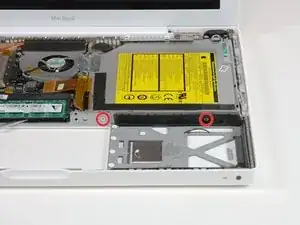
Remove the 2.8 mm Phillips screw securing the optical drive.
-
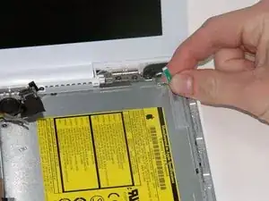
After removing the screw, push the metal tab backwards, towards the fan, to release the front of the optical drive.
-
-
-
Remove the following 3 screws:
-
Two 3 mm Phillips near the right speaker.
-
One 6 mm Phillips threaded through a hole in a plastic finger above the subwoofer.
-
-
-
Using a spudger, gently pry up the white plastic slot and slide the metal c-channel to the right and away from the display.
-
-
-
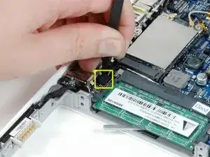
Use a spudger to carefully disconnect the microphone cable from the logic board. You'll want to work from side to side, and slowly wiggle the connector out of its socket.
-
-
-
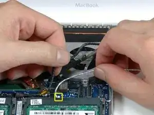
Lift up on the black right speaker cable with one hand, and deroute the silver microphone cable from the silver metal clip just above the right RAM slot.
-
-
-
Deroute the silver microphone cable and gray display data cable from the tabs at the bottom of the subwoofer.
-
-
-
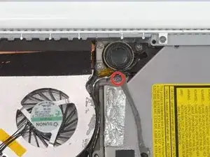
Remove the single 3.2 mm Phillips screw securing the ground loop in the display data cable located just above the Bluetooth board.
-
-
-
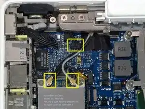
Disconnect the two antenna cables from the Airport card, and the black inverter cable from the logic board. (Pull vertically on all three.)
-
-
-
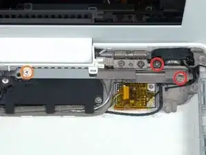
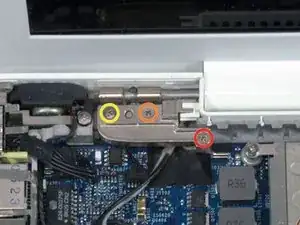
Remove the following 2 screws from the right hinge mount:
-
One 6 mm Phillips on the left side of the hinge mount.
-
One 10 mm Phillips on the right side of the hinge mount.
-
Lift the right hinge mount out of the computer.
-
-
-
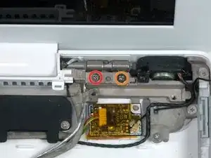
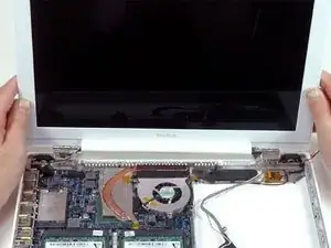
Hold the display with one hand while removing the screws from the left hinge mount.
-
Remove the following 3 screws from the left hinge mount:
-
One 6 mm smaller diameter Phillips from the right side.
-
One 6 mm larger diameter Phillips from the middle.
-
One 10 mm Phillips from the left side.
-
Lift the left hinge mount out of the computer.
-
-
-
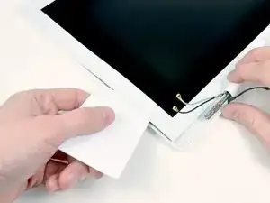
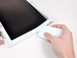
Use a thin plastic card to release the tabs and their clips holding the front display bezel to the display assembly. There are five tabs along the left side of the display bezel.
-
-
-
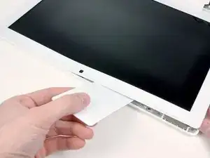
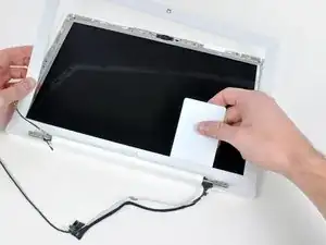
Lift up the front display bezel from the top and use your plastic card to free the tabs along the bottom edge of the display bezel.
-
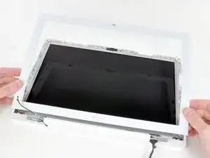
After freeing all holding tabs, lift the front display bezel away from the display assembly.
-
-
-
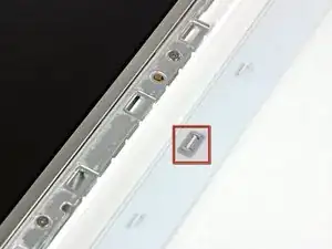
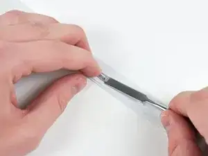
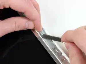
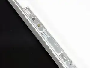
Use a metal spudger or another thin tool to carefully pry the gray plastic clips off the tabs molded into the front display bezel. A 0.8mm flat screwdriver may be useful for this step. You may find that it's easier to remove some of these clips by prying up on their long sides.
-
-
-
Insert one end of the retaining clip beneath the edge of its recess cut into the LCD bracket.
-
Use the edge of a spudger to push the short hook tab on the underside of the other end of the retaining clip into the recess cut into the LCD bracket.
-
-
-
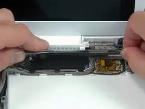
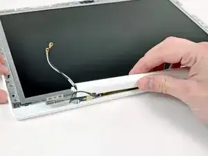
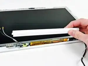
While holding the display down with one hand, use your other hand to lift the left end of the clutch cover off the clutch hinge and guide the inverter cable and AirPort cables through the gap in the clutch cover. If the cables snag on the two hooked tabs on the inside end of the clutch cover, free them carefully.
-
-
-
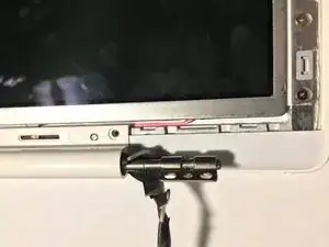
Lift up the right end of the clutch cover while guiding the display data and iSight cables through the gap and the two hooked tabs at the right end of the clutch cover. If the cables snag on the two hooked tabs, free them carefully.
-
Lift the clutch cover off of the display assembly.
-
-
-
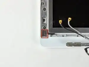
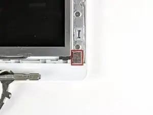
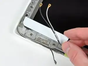
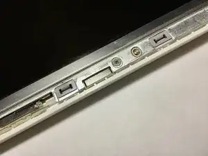
Remove the small piece of foam tape stuck down above each of the bezel covers, at the lower left and right corners.
-
-
-
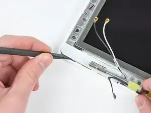
Use a spudger to slide the left bezel cover towards the LCD panel.
-
Lift the left bezel cover off the display assembly.
-
-
-
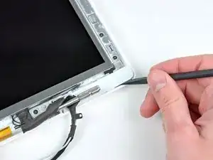
Use a spudger to slide the right bezel cover toward the LCD panel.
-
Lift the right bezel cover off the display assembly.
-
-
-
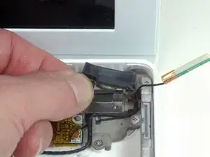
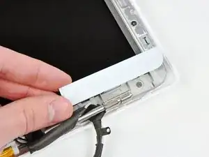
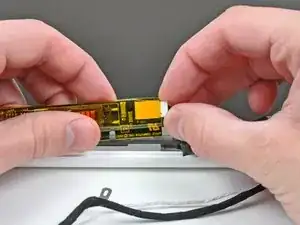
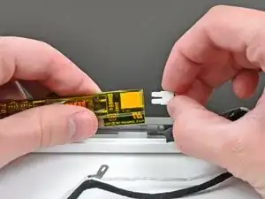
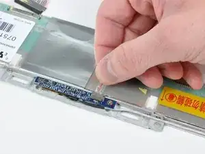
Lift the inverter out of the display slightly and disconnect the backlight cable from its right side.
-
Place the inverter back down in its recess.
-
-
-
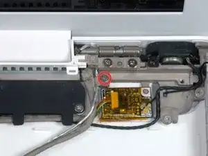
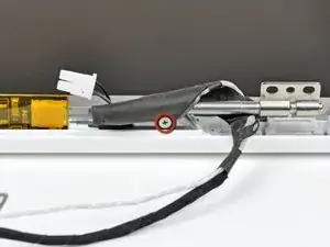
Remove the single 3.2 mm Phillips screw securing the display data cable to the right clutch hinge.
-
-
-
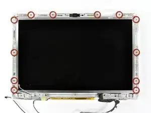
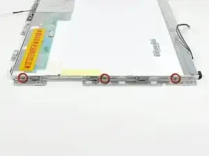
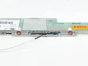
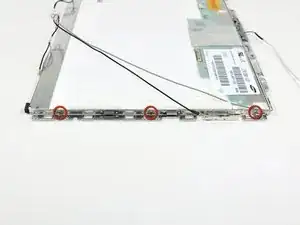
Remove the twelve 4.2 mm Phillips screws securing the LCD assembly to the rear display bezel.
-
-
-
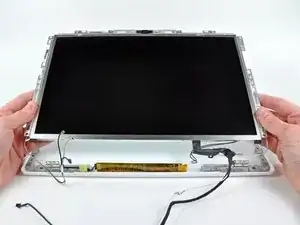
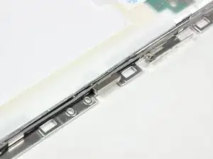
Raise the bottom edge of the LCD assembly slightly, then slide it down slightly to free its upper edge from a slight overhang in the rear display bezel.
-
Lift it out of the rear display bezel, minding any cables that may get caught.
-
-
-
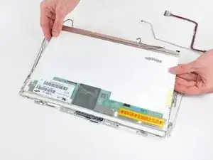
Turn the LCD panel assembly over so that the screen is face down. You may want to use a cloth on your worksurface to prevent scratching the screen.
-
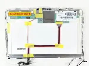
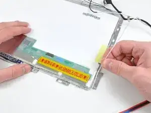
Peel up all the yellow tape securing the display data and iSight cables to the back of the LCD panel.
-
-
-
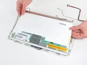
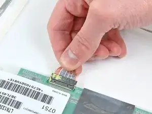
Lift up the display data and iSight cables and move them to the side. It is not necessary to entirely remove these cables from the display assembly.
-
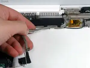
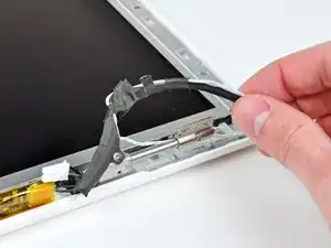
De-route the microphone cable from the right side of the LCD assembly.
-
To reassemble your device, follow these instructions in reverse order.
One comment
Fantastic directions!!! Saved me hundreds and gave new life to Macbook. Thanks!

This is a difficult project. It is imperative that you read the entire guide before you proceed. Have a system in place to keep track of the screws so you know what goes where. Budget several hours for this.
jonathan55 -