Introduction
Charges battery and connects battery to logic board.
Tools
Parts
-
-
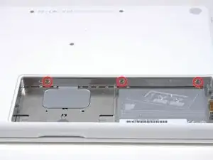
Unscrew the three evenly-spaced Phillips screws from along the rear wall of the battery compartment.
-
-
-
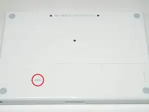
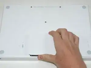
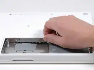
Grasp the right end of the L-shaped memory cover, then pull it towards you so it clears the battery compartment opening.
-
Lift the memory cover up and out of the computer.
-
-
-
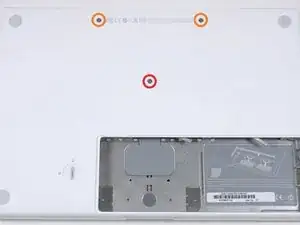
Remove the following 3 screws:
-
One 11 mm Phillips#00 in the middle of the lower case. (Head: 5mm dia. x .75mm thick)
-
Two 14.5 mm Phillips #00 (Head: 5mm dia. x .75mm thick)
-
-
-
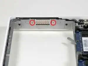
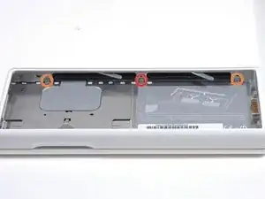
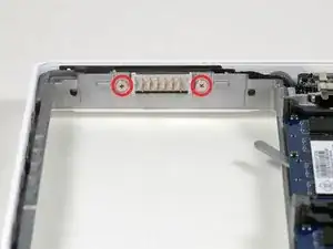
Remove the following 3 screws from the rear wall of the battery compartment:
-
One 3 mm Phillips #0. (Head: 2.75 mm. dia.)
-
Two 4 mm Phillips #0 on the either side. (Head: 2.75mm dia.)
-
-
-
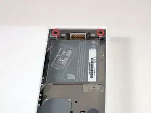
Remove the two Phillips screws from either side of the right wall of the battery compartment (not the ones closest to the battery connector).
-
Two 6.25 mm Phillips #000. (Head: 4 mm. dia. x .5mm thick)
-
-
-
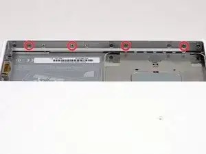
Remove the four indicated Phillips screws from the front wall of the battery compartment. When working from the left, remove the 2nd, 4th, 7th and 9th screws.
-
Four 3.25 mm Phillips #000. (Head: 4 mm. dia. x 4mm thick)
-
-
-
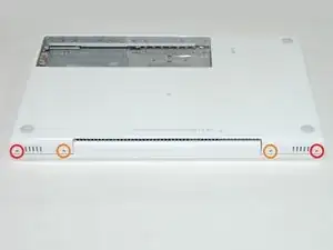
Remove the following 4 screws from the back of the computer:
-
Two 11 mm Phillips #00, with Shank (2.2mm dia. x 2 mm len.) (Head: 3.2 mm. dia. x .5mm thick)
-
Two 7.25 mm Phillips #00, with Shank (2mm dia. x 3.75 mm len.) (Head: 3.2 mm. dia. x .5mm thick)
-
-
-
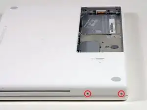
Remove the two Phillips screws from the optical drive (right) side of the computer:
-
Two 5.2 mm Phillips #00, with shank (2.3mm dia. x 3.25 mm len.) (Head: 3.2 mm. dia. x .5mm thick)
-
-
-
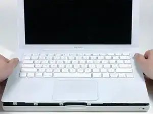
Use a plastic opening tool, an expired plastic credit, or a similarly-thick card to pry up on the upper case, starting in the upper-left corner and working around to the front of the computer.
-
-
-
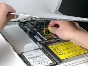
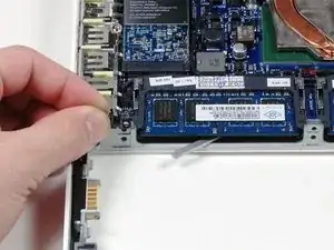
While holding up the upper case, pull up the black tab on the connector end of the silver ribbon cable away from the connector's socket on the logic board.
-
-
-
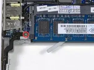
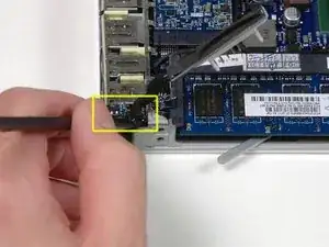
Use a spudger to carefully pry the battery connector up and disconnect it from the logic board.
-
Look at the pinout on the bottom of the battery connector circuit board. If there's no gap in the two rows of pins (if both rows contain ten pins), it's the Non-Energy Star version. If there is a gap (two rows of six pins each, separated from two rows of three pins each), then it's the Energy Star version. These two versions aren't interchangeable.
-
To reassemble your device, follow these instructions in reverse order.
4 comments
plz add screw size
Im sad i did this one + Replacing MacBook Core 2 Duo Magsafe Board, try another charger and still the same symptoms :( wont charge and green light stay on. waste of time and money for my Macbook 2.4Ghz intel core 2 DUO White.
Did you ever resolve the issue? If so, what was the problem? Thank you.
My battery connector looks like the energy star (6+12 pins) but on the motherboard says “apple inc 820-2279-A “ and no ‘energy star’ is written. I assume I should get the energy star model because is identical to mine. However, iFixit points to follow what is written on the board. So, something wrong here…
daniel -

I used this guide plus the Thermal Paste guide to resolve my MacBook RRS (Random Restart Syndrome) issue. My MacBook would randomly restart after the fan kicked into high speed. When I removed the heatsink I discovered an an irregular patch completely free of thermal compound of about 15-20% of the area on one of the processors. I removed and re-applied the thermal paste. I ran a memory test utility overnight that previously caused a restart after a couple of hours, and the probelm seems to be solved. TIme will tell.
ServiceDocs -
This guide was seriously helpful, so thanks for putting this together. I found a thick ribbon of dust/muck whatever between the fan outlet and the exhaust port that was almost as dense as felt. My fan must have been fighting like crazy trying to pass air through that blockage, which explains the high temps and excessive fan noise. Wish I'd done this sooner...
Thanks again!
skraggle -
Just R&R'ed the fan in my black MacBook Core 2 Duo tonight. Took me 30 minutes tops and I was taking my time. These instructions are SPOT ON! Great job ifixit.com! Two thumbs up!
Follow the instructions exactly as you see and have a piece of paper taped to the table next to you that you can outline all the screws you took out so you know where they go back in. I expected this to be a LOT harder, but it was one of the simplest repairs I've ever done to ANY computer!
mikeutter -
Piece of cake--or should I say gum. If you don't have a magnetized screwdriver, load up a stick of gum and chomp on it until it's needed then use a bit to retain screw on the driver. And if you should tear the black tape, or if the silver tape won't stick any more, just bubblegum it together. The instructions were clear and correct, which made for a very simple repair.
Mike Woodruff -
My battery does not pop out when after step 1. Any idea why, and how do fix it?
Calvin -
Will not drop out even if you turn it upside down?
skraggle -
Somehow, now my isight camera doesn't work and the light is always on. Cannot figure out what I did wrong.
josefsalyer -
Somehow the plastic disc with the slot for a coin got dislodged from the case, and I can't seem to get it open now. Any tips/links on how to open this without the aid of the plastic disc?
Peter Wood -
i broke my disc off as well. I used two toothpicks to rotate the thing. hi tech.
howard bederman -
Outstanding guide - thank you!
owen bullock -
My computer will not charge when plugged in. It will stay on as ling as the plug is in the wall however if the power source gets disconnected it will shut down immediately. I removed the battery and put it back in that did not help. It worked and charged fine 2 days ago. I have a backpack with a laptop storage area. I went to hang the backpack up and it fell and ever since the battery is not functioning. Is there some fix I can try or is my only solution to replace it? I would have thought that dropping it would affect more than the battery?
Beth Tomasek -
Better leave the back pack where it cannot fall. Hindsight is so much better than foresight . I learned the hard way too!
Loy Lum -
Many of the tiny screws in this project were quite sticky. I found some blue Loctite residue that must have been when the Apple repair shop worked on the laptop years ago. I have found that it is important to hold the correct driver firmly down in the screw and then just tweak the driver in short bursts to loosen it before unscrewing it with a smooth turn.
Patrick Langvardt -
Be really careful while doing this to not use too much force while doing this step, because the plastic disc can break off and it can be a cosmetic issue along with functionality issue. This happened to me first hand so please take my word for it…
[deleted] -
Probably worth mentioning at this stage that the caddy you propose to use should not have lugs on the front corners, like those used in unibody 1278 and onwards.
harwood -
Hehe, still my mac os running! After, already bit more than 10 years of use!
I put new heat paste now for the second time. Maybe this helped for staying young so long.
Thanx for all the repair guides!!!
Fabien -