
Introduction
Prerequisite-only guide to slide the logic board and attached components out of the Mac mini's chassis.
-
-
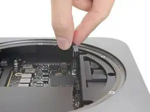
Grasp the power supply cable and lift to disconnect it from the logic board, wiggling as needed to loosen it up.
-
-
-
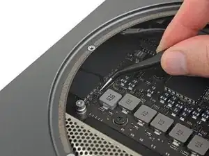
Carefully lift the connector for the LED indicator light straight up to disconnect it from its socket on the logic board.
-
-
-
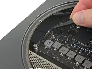
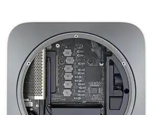
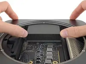
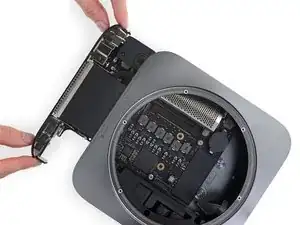
Place a thumb at each end of the exhaust vent, over the fan screw holes.
-
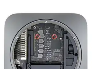
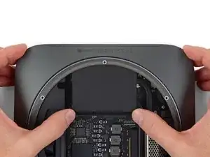
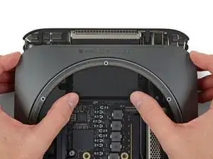
Push firmly in the direction of the ports until the logic board unclips and begins to slide out of the Mac mini.
-
Conclusion
To reassemble your device, follow these instructions in reverse order.

Loosen the side nearest outer case first
dermoid777 -
Is that a standard 20 pin power connector?
gotjoshua -
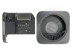
It appears there are curved metal tabs (1 on each side of the connector) that compress until they lock the connector in place or the connector is removed, but doing so evenly as to not break off the 2 gold knife blades on the logic board that slide into the plastic connector. Both the tabs & gold knife connectors are seen in the 2nd picture, in the first picture you can see how the tabs look when they are locked into the logic board connection.
bbbb -