Introduction

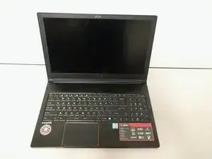
Replacing RAM or NVMe in the Stealth Pro. In order to replace the RAM or NVMe in the Stealth Pro, you'll have to remove some other parts that get in the way.

  1. DLmYaJwOqwdIodNw
    DLmYaJwOqwdIodNw
    FbFuftomwXQENcKU
    EI4Hy4RmgQqSAqeM
    • Turn off the laptop before proceeding.

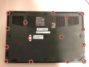
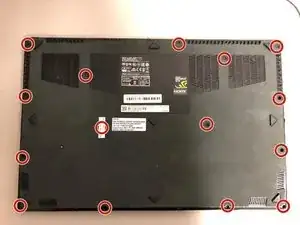
    • Unscrew the 15 screws on the bottom panel using a Phillips #00 screwdriver.

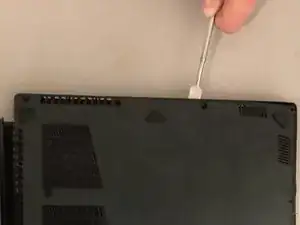
    • Pry open the back cover with a plastic prying tool.

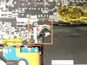
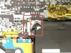
    • Unplug the battery cable from the motherboard to prevent a ground fault. Either use your hand or a pair of tweezers to unplug the battery cable.

    • Too much pressure from the spudger can break the clips that secure the back panel, but some flex is not dangerous.

    Note that the back side panel (the one with “Stealth” written on it) also comes off. This makes it easier to open without breaking the clips. Take care not to insert the prying tool you use too far in on that side as there is a ribbon cable for the power LED very close to the side located in the center.

    Philip Schalkwyk -

    Hi, there are two kinds of screws. One are longer than the other. Can you please tell me where the longer screws go ?

    jd-cure -

  2. 3SZeXEdTrLhfaRnJ
    3SZeXEdTrLhfaRnJ
    jNbgIKRcrts1k5wQ
    Klni1CSVXTZAxRj5
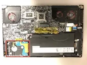
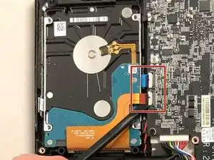
    • Disconnect the SATA cables from the motherboard using a plastic spudger.

    • Gently pull out the SATA cables out of the ports.

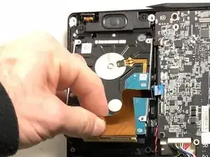
    • Grab the auburn color cable and lift up the hard drive. Slide out the hard drive while holding onto the cable.

    • Cables are fragile. Do not apply excessive force.

  3. OgMHk6FnIWSiZRhn
    • Before you begin, be sure to turn off your laptop and discharge the battery down to 25%.

    • Use a Phillips screwdriver to remove the 15 screws securing the back cover.

    • Insert an opening tool or spudger in the seam and pry along the perimeter to loosen the back cover.

    • Do not insert the opening too too far into the back edge (with "Stealth" written on it), or you may damage the power LED.

    • The back cover is secured with clips. Too much pressure from the spudger can break the clips, but some flex is not dangerous.

    • Remove the back cover.

  4. jdjwFnnDfaLkL2Dh
    • Disconnect the battery by carefully pulling its connector towards the battery.

    • Pull parallel to the battery, not straight up.

  5. REFZk4Aw1pcFQKGA
    REFZk4Aw1pcFQKGA
    mMuPqD5kKZrBkipu
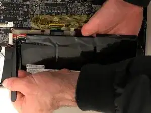
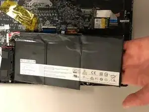
    • The battery is attached to the laptop with a strong adhesive.

    • Lift the battery from laptop.

    • Be careful not to bend the or puncture the battery, as that may cause a fire hazard.

  6. 24rCtuOtbDAu3YUX
    24rCtuOtbDAu3YUX
    sPYgsJEC2QWjA1fG
    KZSkMKGUH1gRDjn3
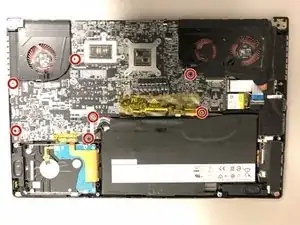
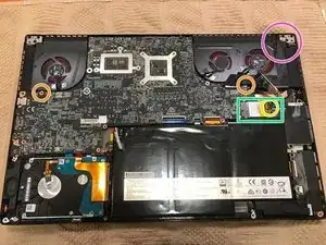
    • Once the battery is out, remove the screws at each standoff with a #00 Phillips screwdriver.

    • Remove the two additional screws under the fans.

    • Remove the screw securing the Wi-Fi card.

    • Disconnect and remove the wifi card from the motherboard.

    • Disconnect the additional cables connected to the motherboard.

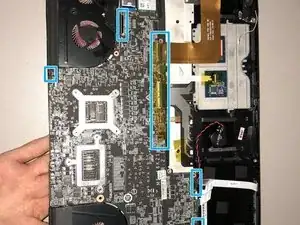
    • Carefully lift the motherboard out of the computer.

    • The screen cable in the top left is short and restricts movement when removing the motherboard.

    This is by far the most difficult step.

    Make sure all the screws are removed before attempting to lift the motherboard. There are more screws to remove than the above picture indicates:

    -One located under the left fan cable

    -Another below the right fan

    -Another holding down the wifi card above the battery to the left (suggest removing this screw then removing the wifi card completely)

    Note that the screen cable is located in the top left corner and cant be disconnected.

    The right speaker will also achor down the motherboard so watch out for that.

    When lifting the motherboard, be gentle and take your time. I lifted the left side about half an inch out first then struggled a bit to free it from the right side I/O ports. Placing it back in is easier.

    Philip Schalkwyk -

  7. nhSZvCgWMLuYMWjq
    nhSZvCgWMLuYMWjq
    Ak5y21F3AYY5Tmms
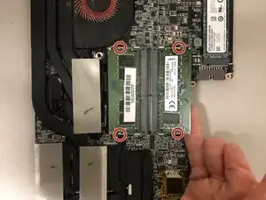
    • After flipping the motherboard over, locate the RAM slots.

    • Release each stick of RAM by carefully prying the metal clips away.

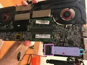
    • Remove M2 screw securing NVME drive.

    • Remove or replace NVME drive.

Conclusion

To reassemble your device, follow these instructions in reverse order.
Zachery Friedman

Member since: 20/09/17

318 Reputation

0 comments