Introduction
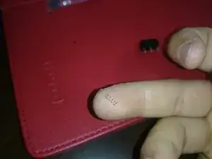
Replacing the Omron D2FC-F-7N switch that is underneath the left/right click mouse buttons on the Logitech G700/G700s mouse.
Parts
-
-
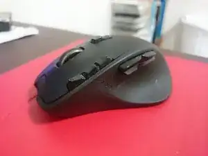
This is my trusty ole Logitech G700. I've had it for a good 7 years at the time of writing this guide! It's about time the switch has died.
-
-
-
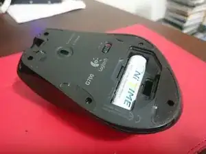
Start by turning off the mouse and removing the back battery cover and battery of the mouse.
-
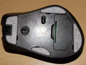
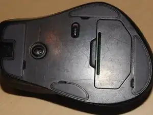
Then remove the teflon "feet" of the mouse to get to the five (5) screws that hold the top and bottom of the parts of the mouse together.
-
If you want to keep the stickers reusable, consider only peeling back the amount you need to get at the screw. Anymore will increase the risk of the glue sticking to the body of the mouse rendering the sticker feeling bumpy and will cause the mouse to track unevenly.
-
If you are using brand new stickers, make sure you clean off any excess glue. I found using the glue stuck to the peeled off sticker extremely useful at peeling off the remaining glue.
-
-
-
Use a small 2 or 3mm screw driver to take out the five screws at the bottom.
-
Keep the screws in a safe place!
-
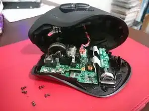
The top and bottom shells of the mouse should open up fairly easily. If not, poke a spludger or guitar pick or even just your fingernail into the split between the shiny and matte plastic and the shell should pop right off.
-
When the top shell comes apart, be careful not to pull too hard as there is a connection wire that connects the side buttons to the upper PCB!
-
-
-
The side button cluster connection cable can be a little tough to disconnect. The socket on mine was REALLY tight but just wiggle the brown connector a little and it should come off.
-
-
-
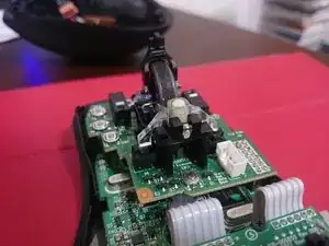
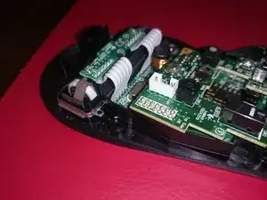
WARNING: Be careful in this section. There are two almost microscopic springs that are part of the mouse wheel. Do NOT turn the mouse up side down after removing the locking pin or you will LOSE them.
-
Rotate the free spin activation arm up (as can be seen in the first picture).
-
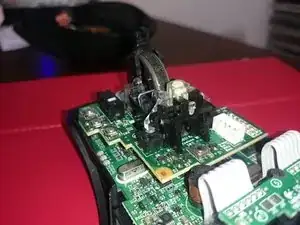
Make a note of the orientation of the locking pin, curved section facing down and slide it out of the socket (as can be seen in second picture).
-
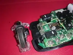
Once the locking pin has been taken out, the entire mouse wheel should lift out of it's resting cradle. Make sure you note the springs (can be seen in the third picture).
-
Do not lose these springs as they serve to give your middle mouse click that "bounce". They are almost impossible to find if dropped. (Yes I did drop mine and I found them again through sheer dumb luck)
-
Store locking pin and springs in a safe location.
-
-
-
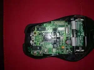
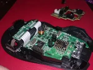
There are four screws to remove here. Two screws are next to where you found the springs and another two that fixes the mouse wheel structure to the upper PCB.
-
Second picture shows the springs... Don't lose them!
-
-
-
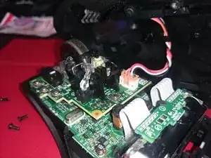
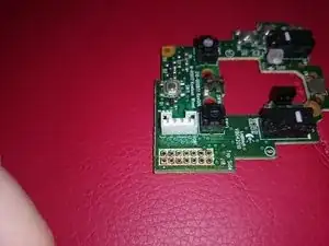
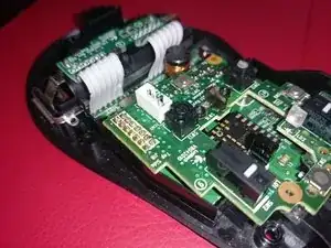
With the screws taken off from the upper PCB, it's time to desolder the connecting pins that connect the upper PCB to power PCB. My preferred method was to use a desoldering braid but I think a solder sucker works too.
-
Careful not to let your soldering iron touch the plastic ribbon cable or the upper shell connector (white in the first photo). You can see I did singe my ribbon cable a little bit haha...
-
Once you've removed the solder from all the pins, you should be able to lift the upper PCB off easily.
-
-
-
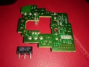
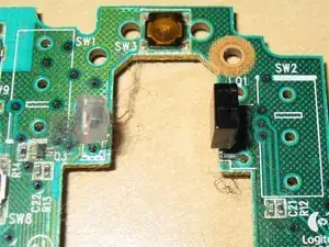
With the upper PCB removed, you can now flip it upside down and desolder the Omron Switch. (Make a note of which way the switch is facing!)
-
Clean off any excess solder from the component mounting point of the Omron switch.
-
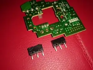
Mount new switch on with the white click button facing the same direction as the old switch.
-
It's okay to burn the switch a little (since it's dead anyways right?) but try not to let the soldering iron touch any of the other solder points when soldering/desoldering the new/old switch.
-
-
-
Remount and resolder the upper PCB then connect your mouse to the computer and check that it still functions.
-
Once everything is confirmed working, reassemble and reconnect everything you took out and you'll have a working mouse again! :D
-

To reassemble your device, follow these instructions in reverse order (Except the removal and installation of the switch, of course...)

8 comments
Das Ablöten des Anschlusses ist relativ aufwändig. Mir sind dabei die Pads kaputtgegangen -> Maus ist jetzt für den Müll
I really recommend NOT doing this.
It is easier and safer to pop the switch cover and replace the metal leaf spring, and that is hard to do , but still easier than desoldering the connection bridge.
gpk -
Yeah this is not for the feint of heart. Everything went smoothly for me the first go around, but had to desolder everything I just did because I mounted the Left Click Switch the wrong way and it wasn’t making contact to click at all. Desoldering the connection bridge for the upper PCB to lower PCB is definitely much harder than it seems and having to do it twice in a row basically killed the solder joints on my upper PCB so ended up having to order a complete new one. Learn from my mistake and triple check the switches and how they go on before you desolder the old ones. The connection bridge really cannot handle too much soldering and desoldering over and over. On a plus side it seems the new PCB coming from Hong Kong has a push connector now on the underside connecting the upper and lower PCBs so no need to solder and desolder anymore if switches need to be replaced. Also, the new PCB is already upgraded to 20M switches form the original 10M.
Raisoko -