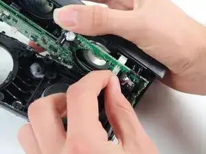
Introduction

  1. YnlnA4A5cB5hX4bZ
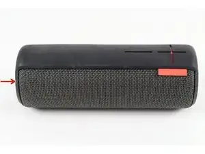
    • Turn the device over. The D-ring will be on the left face of the speaker when viewing the device from this orientation.

  2. ZUHnoi6e5ScLc2F3
    ZUHnoi6e5ScLc2F3
    OkRGCmfcoZTBaGXy
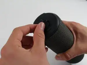
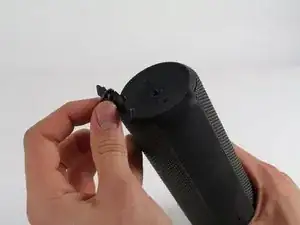
    • Lift the handle on the D-ring and unscrew it.

    • Remove the D-ring.

  3. OyrdPMyALqWWKtr2
    • Any repairs made from this point forward will void your device's warranty.

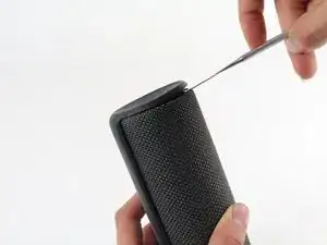
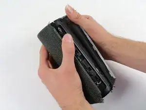
    • Holding the speaker upright, wedge the metal spudger in between the casing and the speaker. Gently pry open the tabs as they are easily broken.

    This part is not easy. The main risk is to broke the plastics clips.

    Optrolight -

    Use a heat gun (or hair dryer on high) first around the edges before attempting to pry it open. There are six tabs: one directly in line with the charging port; one approx 3/4 inch to the left and right of that tab; one centered against the back of the volume control "panel", and one approx 3/4 inch to either side of that one. So when prying, try to insert your spudger in between those spacings in order to not push on the tabs directly.

    Lotus Flower -

  4. TRBvaJSG5KNCXfBf
    TRBvaJSG5KNCXfBf
    YgLS3FBs1yFpqRr3
    q5EWYjOYvNlkvTRv
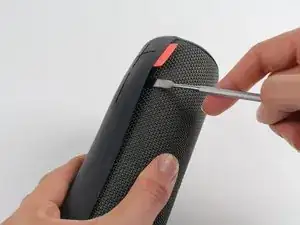
    • Find the part of the casing that covers the volume controls. Wedge the metal spudger under this and pry open all of the tabs as in the previous step.

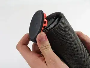
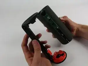
    • Repeat for the bottom of the speaker and pry the casing open with your fingers.

  5. aMJOLjlFTeG4bRwn
    aMJOLjlFTeG4bRwn
    SRjRlgjeJnVEeduA
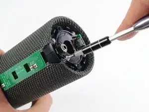
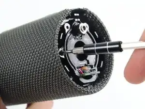
    • Using the Phillips J0 head screwdriver, unscrew the four silver 9 mm screws.

    • Do the same for the two black 7 mm screws.

  6. oPqssBfC6ZDxmFKj
    oPqssBfC6ZDxmFKj
    jDQTlFMRdUksISIn
    vWZ6ZlueCYCy5Ppk
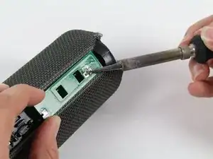
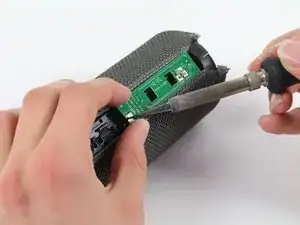
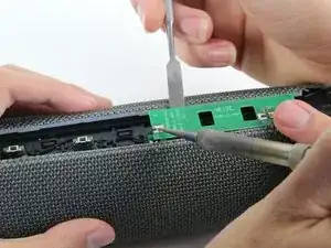
    • This next step involves the use of a hot soldering iron. Remember to be careful during this step since it can be easy to burn yourself.

    • Using a soldering iron, de-solder the two ends of the switch plate.

    Great instructions here guys - just one comment from myself - underneath the plate there is glue holding it down as well as the solder joints. Be sure to heat it up slightly prior to lifting out otherwise the capacitors and other components get stuck in the glue.

    Jamie Horn -

    bei mir sieht der blootooth-adapter anders aus. da muss ich nix löten, er ist klein und liegt nur in einer passenden mulde, aus der er herausgehoben und in die er wieder abgelegt werden kann. meine typbezeichnung ist S-00122.

    thomas propp -

    Definitely start with the middle one, has 2 solder hinge points that took me a couple minutes to heat up, wiggle and finally lift up. One that side lifted, was much easier to go back to the edge hinge, heat up and just gently pull off.

    Michael Arvan -

    It is importante to note that there are two large solder hinge points and for the midle to pin point. Easy to desoldering but not easy to soldering after battery replacement.

    Optrolight -

  7. UsBekJvobsb4OAY1
    • With the switch plate disconnected, remove it and your device should now look like this.

  8. NC1PGBVJL5xKtfrV
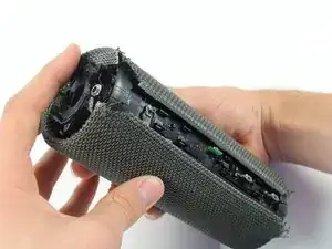
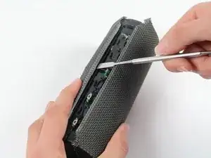
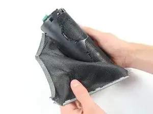
    • With a metal spudger, pry open the tabs on the speaker sleeve along the length of the speaker.

  9. AkCHJRMYTrWWejjj
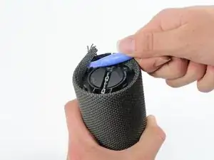
    • Use a plastic opening tool to pry the sleeve off from the bottom of the speaker.

    Zuerst auf der Gegenseite zuerst den Deckel, dann die Hülle lösen. Erst am Ende die Seite mit dem Power Button.

    Hans Fuchs -

    Translation: First loosen the cover on the opposite side, then the cover. Only at the end the page with the power button.

    Dan -

    A tips that could be help lot of us. i consider it what not easy to pry the sleeve off. But in fact there are many hole around the side that could be used to push through the holes, the plastic ring retainer.

    Optrolight -

  10. EHNBetUFlThiBcdX
    EHNBetUFlThiBcdX
    ZfnhSKEq1MSfpnce
    nIF2npvqCUXjXpkH
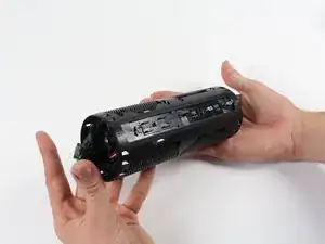
    • Peel off the sleeve.

  11. VrV2FZjmxgmagAjc
    VrV2FZjmxgmagAjc
    mIOdAWdUFjEcI5GI
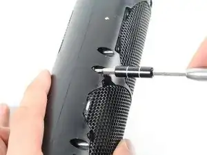
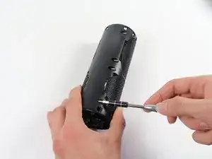
    • Use a Phillips 1 screwdriver to unscrew the eight black 14 mm screws along the length of the casing.

  12. eXeOLdX6kItOEWuf
    eXeOLdX6kItOEWuf
    r1XUK12YCnUTql6F
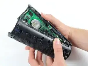
    • With the screws removed, pry open the casing to be able to get to the components inside.

    • Try prying the case open from one of the ends if that is easier.

  13. CqYiDTojj6LXKjub
    CqYiDTojj6LXKjub
    V1Y224N4DQfsYmZX
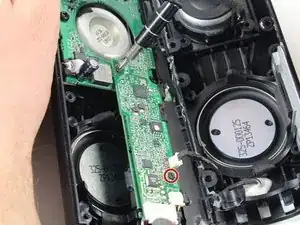
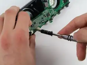
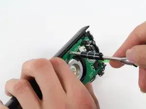
    • With a Phillips #00 screwdriver, unscrew two 5.6 mm screws from the rectangular shaped circuit board.

  14. HWEEYWtNJtvgOSB1
    • With the Phillips #2 screwdriver, unscrew the 9.9 mm screw from the larger circuit board surrounding the speaker.

  15. bxGlI2pX4FYd4ttG
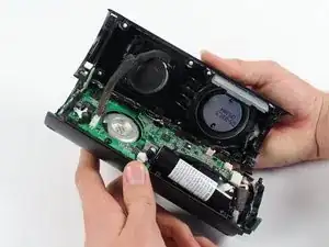
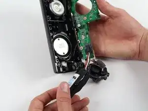
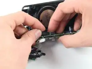
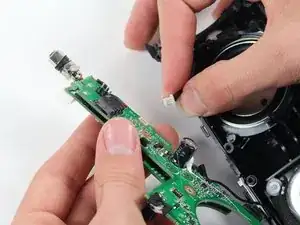
    • Once all of the screws are gone, you should be able to remove the circuit boards and find the battery.

  16. vJ3WfTgmATDZL3OE
    vJ3WfTgmATDZL3OE
    nF1cAPB2CtGGOTQQ
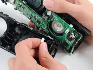
    • Remove the battery by pulling it from the terminal as marked in the picture.

  17. GG1iQVPsrLYKoXeF
    GG1iQVPsrLYKoXeF
    pr4BLbWDtV6OEnoF
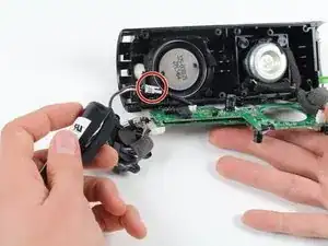
    • Remove the speaker by pulling it from the terminal as marked in the picture.

  18. jAMmt1LAbMSnotkX
    jAMmt1LAbMSnotkX
    JZdAXolDAmQOKO5C
    • Remove the second speaker by pulling it from the terminal as marked in the picture.

  19. uvMFJCnNoHSpvv53
    uvMFJCnNoHSpvv53
    TmRIVxf45P11EKaf
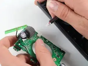
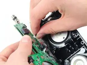
    • Finally, remove the motherboard completely by pulling it from the terminal as marked in the picture.

Conclusion

To reassemble your device, follow these instructions in reverse order.

Sean Reilly

Member since: 01/10/15

1715 Reputation

2 comments

Is there anywhere I can buy the motherboard to replace my UE Boom board fried by lightning?

Mohd Razali Hamid -

I would like to know where can I buy the UE BOOM Mother Board.

許志豪 -