Introduction
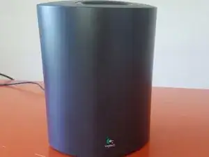
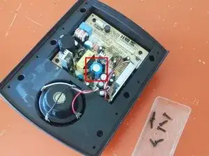
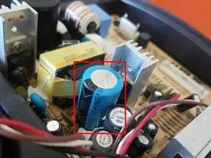
The purpose of this repair is to fix crackling or sizzling subwoofer that may give unpleasant sounds. Most of the times the sizzling sound appears gradually along with the use of these speakers. It is mostly caused by a over-stressed capacitor : generally the circuitry of the cut-off is badly designed and the capacitor is shortened. Sometimes the damage to the capacitor can be observed as the top of the capacitor has a curved shape. Sometimes it is not visible. I replaced that capacitor with a higher-grade component : here a capacitor dedicated to the automotive industry.
Tools
Parts
-
-
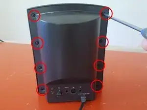
Remove the 8 screws from the rear panel with a #01 philips screw driver
-
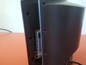
Keep the screw drivers aside and smoothly separate the two halves of the casing.
-
-
-
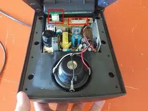
Gently unsnap the connection pins on the right of the picture.
-
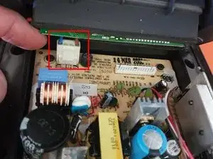
Smoothly unsnap the connector of the power supply attached to the main board. Don't try to pull these connectors : you may damage the power chord and get more repairs to do.
-
-
-
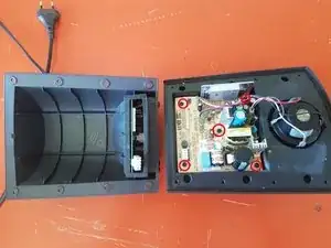
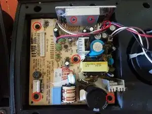
Remove the 5 screws binding the main board to the casing. Use a #01 Philips screw driver.
-
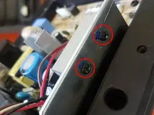
Remove the 2 screws that binds the heat sink to the metal plate of the casing. Use a #01 Philips screw driver.
-
-
-
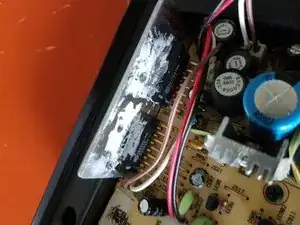
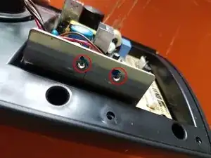
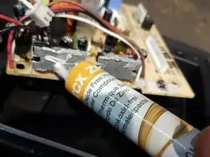
Make sure you have removed the heat sink of subwoofer drivers and the 7 screws.
-
Unsnap at least one connector that links the main board to the woofers.
-
-
-
Use a soldering iron to remove the dysfunctional capacitor. Use desoldering braid and clean the PCB if you see electrolytic leakage.
-
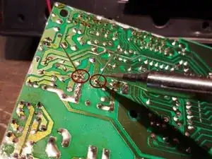
With the soldering iron solder the spare capacitor to the main board with the negative terminal in the same hole as the previous capacitor.
-
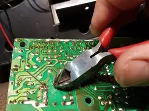
With a cutting plier cut the terminals of the capacitor as close as possible to the main board. This will avoid any risk of circuit shortening and new damage to the subwoofer.
-
Please follow the previous steps in the reverse order to finish this fixing and enjoy listening to clean sound again.
One comment
The only difficult part is putting the thing back together.
