Introduction

This is a prerequisite only guide. It disconnects most of the connectors and removes most of the screws to take the motherboard out. The shots are taken such that you can’t see whether the Taptic Engine is out or not.

Note that each iPhone's logic board and Touch ID fingerprint sensor are paired at the factory, so replacing the logic board will disable Touch ID unless you also install a replacement home button that has been properly paired to your new logic board.

Opening the iPhone 8 will damage the waterproof seals on the display. If you do not replace the adhesive seals, your phone will function normally, but will no longer be water-resistant.

  1. fBkYimJSyuQUTs3Y
    fBkYimJSyuQUTs3Y
    2mwxZyuAjalqsABR
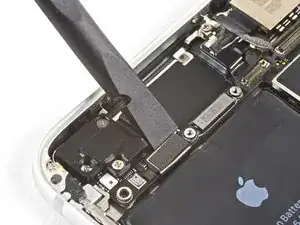
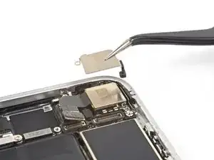
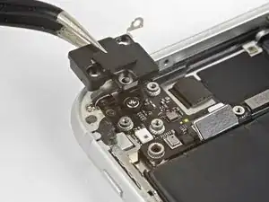
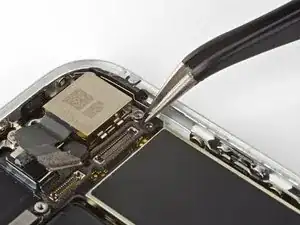
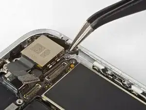
    • Use the flat end of a spudger to disconnect the camera cable connector by prying it straight up from its socket.

    When replacing, used iFixit tweezers to gently hold/bend the cable, and used my finger to press the connector back in place. This was the best way I could get the connector lined up and seated properly.

    Habel -

  2. aimokbie2aoPneTg
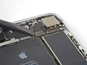
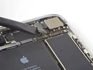
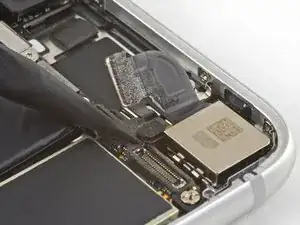
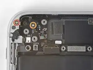
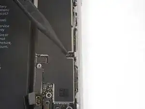
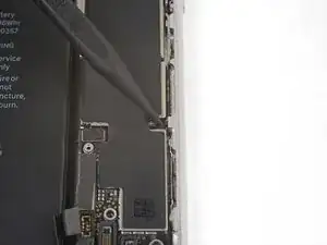
    • Remove the two screws securing the rear-facing camera bracket:

    • One 3.0 mm standoff screw

    • One 3.1 mm Phillips screw

    • Standoff screws are best removed using a standoff screwdriver or bit.

    • In a pinch, a small flathead screwdriver will do the job—but use extra caution to ensure it doesn't slip and damage surrounding components.

    The screw and standoff are the other way round in this step. The photo shows the small screw removed and the standoff securing the logicboard is circled incorrectly. Also you may find that the standoff screw is not magnetic, making it a little tricky to replace!

    Michael Millington -

    Hi Michael,

    You are correct; thanks for catching that! The original image was correct, and for some reason the image was updated, and no longer correct. I have reverted it back to the original image.

    Arthur Shi -

    wrong Screws in Picture

    mmiller -

    Be careful when reassembling. These screws came demagnetized for me in the process, and they’re really hard to put in if that happens.

    Nick Cox -

    These screws are not magnetized! If you are trying to put them back, use some tweezers to align them, and while still using the tweezers, grab your standoff driver and push down, then you can screw it in with ease.

    Sean - Lua Tech -

    Thanks for the tip.

    Habel -

    I used a 1.5mm flat screwdriver to do the one with the standoff bit.

    Habel -

  3. G3NTgbRppKnO3Vvs
    • Remove the rear-facing camera bracket.

  4. Sw1lIUFX6vUIHCBQ
    Sw1lIUFX6vUIHCBQ
    ofFfpAW1RgsRpANJ
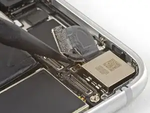
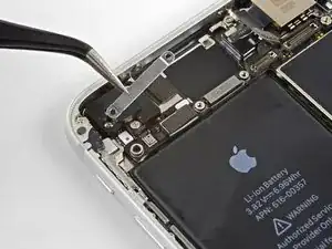
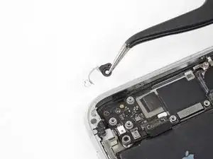
    • Use the point of a spudger to disconnect the flash connector from its socket by prying it straight up.

    The small connector is not actually for the flash, the flash and mic module are just below that and connect to the same cable as the power button.

    Bonrad C -

  5. avsyRIbNSUDPbQH1
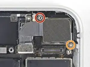
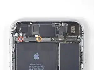
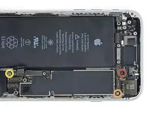
    • Remove the two screws securing the upper cable bracket:

    • One 2.9 mm Phillips screw

    • One 1.3 mm Phillips screw

    Logically - one wouldn’t need to take out all these things to take out something at the bottom of the phone - but in order to get good access to it, you must remove the logic board - which is long and all the way up at the top connected to the antenna. Follow the steps - it works.

    Chris Rainone -

  6. YIULCN3G3pOOh2PK
    • Remove the upper cable bracket.

  7. 6ipn3yVCkkSsFvpT
    6ipn3yVCkkSsFvpT
    2sPCFUfxWjVb6SQ2
    • Use the flat end of a spudger to pry the upper cable connector up from its socket.

  8. Py1VN1v4AL6JCXpZ
    • Remove the three Phillips 1.3 mm screws securing the top left antenna component.

    1,2mm ! not 1,3mm ! thx

    Boni Zei -

  9. 2MqZMfFGSCPfrufm
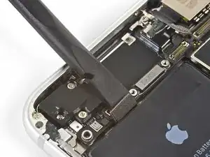
    • Remove the 1.4 mm Phillips screw securing the antenna component to the top of edge of the case.

    Be careful not to strip this screw...I did and I'm going to try to proceed without taking off the antenna component.

    Jacob Steineke -

    Update: You can still go on with the replacement if you do not take off the antenna component

    Jacob Steineke -

    I think this screw is stripped on my iPhone , shittt. So I can just skip this part? or what?

    Jesse henrique -

    If you can avoid putting in battery after this screw, that’ll be easier. I wound up using bit only with my fingers to get an initial thread going.

    anonymous 6745 -

  10. o1lJobSGWjCAoarS
    • Remove the antenna component.

    This is the GPS antenna module.

    anonymous 6745 -

  11. CwGxGAWfNwrGDx2S
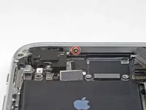
    • Remove the two Phillips screws securing the grounding clip at the top left edge of the logic board:

    • One 1.5 mm Phillips screw

    • One 2.6 mm Phillips screw

  12. FbVuHIZAOCBN6hFQ
    • Remove the grounding clip.

    what happen if don't put this part?

    albert saens -

    Hi Albert,

    It’s hard to tell. Most phone functions will probably work, but you may start getting quirky problems.

    Arthur Shi -

    If it comes out it must go back in *no spare parts *

    Josh Brito -

    J'aurais plutôt dit "...le câble de mise à la masse"

    RobertAncet -

    Bonjour @roroancet, merci beaucoup de votre remarque ! Cela nous a donné l'occasion de plonger dans l'univers de l'électricité ! Il s'avère ainsi que la mise à la masse est le terme approprié ici. J'ai corrigé notre erreur. La prochaine fois, n'hésitez pas à le faire vous-même. iFixit est un wiki modifiable par tout le monde. Encore merci pour votre attention !

    Claire Miesch -

  13. mphtGZonpROuQLJq
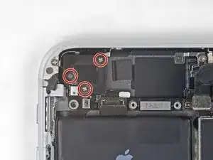
    • Remove the three screws securing the motherboard:

    • One 1.8 mm Phillips screw

    • One 2.5 mm standoff screw

    • One 2.2 mm standoff screw

    The One 1.8 mm Phillips screw was buried under some gasket material. It took some twezzer work to get that material off.

    I.T. Service Desk -

    this is probably the most difficult part because the ‘top 2.5 mm on my version was under a piece of ribbon cable that had to be pulled back. Also notice - this picture is inverted. So the locations are reversed (obviously for clarity)

    Chris Rainone -

    The 1.8mm was indeed buried.

    fotoband -

    Buried 1.8mm Phillips easily located under the gasket material by zooming in on the photo to see position relative to connectors. Material is fibrous, so be patient.

    Ben Sandness -

    I’ve been searching on internet about the black stickers on those parts in the phone and I found nothing about them, what are they? Electrical Tapes? Does it make any differences if we remove them? If yes is, there anything else we can use to replace them? We’re they are for any specific purposes? Thanks in advance if anyone can help me understand

    EverWill -

    Used a 2.5 mm flat screwdriver for both of the standoff screws. There was definitely black adhesive covering the 1.8mm Phillips. As Ben Sandness said, take your time, keep working at it.

    Habel -

  14. wXtgJV1PR6pFVMNO
    wXtgJV1PR6pFVMNO
    cgJYaoRCSMIUmJeh
    • Use tweezers to gently bend the logic board grounding bracket out of the way.

  15. DhlVnBjIRFmBVTLe
    DhlVnBjIRFmBVTLe
    pPYRMetrPaRsdlHW
    • Use the point of a spudger to move the SIM card eject plunger out of the logic board's way.

Conclusion

To reassemble your device, follow the above steps in reverse order.

Take your e-waste to an R2 or e-Stewards certified recycler.

Repair didn’t go as planned? Check out our Answers community for troubleshooting help.

Arthur Shi

Member since: 03/01/18

248651 Reputation

0 comments