Introduction
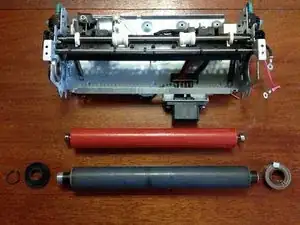
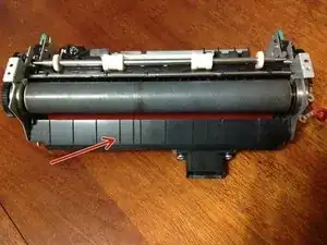
Replace the upper heated roller and lower pressure roller within the fuser unit for Lexmark printer models T630 T640 T642 T644 T650 T652 T654 X651 X652 X654 X656 X658.
This guide starts after the fuser unit has been removed from the printer.
Tools
-
-
Remove these two 6mm #2 screws from the two ends of the heating element and carefully withdraw the glass heating element.
-
The glass heating element is shown in the second picture.
-
Remove these two 6mm #2 screws attaching the top cover.
-
Remove this screw attaching the red power cable.
-
Unplug the pair of yellow wires and unhook them from the hooks tucking them in place.
-
The top cover can now be removed.
-
-
-
Insert a wedge under each of the two spring support arms to lift the two springs.
-
The second picture shows a suitable wedge. This example was made from a toothbrush handle.
-
-
-
Use circlip pliers to remove the circlip attaching the cogwheel to the top roller.
-
Slide this metal catch upwards to release the bearing from its holder. Remove the bearing.
-
The top roller can now be removed.
-
The red pressure roller is now visible with its bearings resting in the holder at each end.
-
To reassemble your device, follow these instructions in reverse order.


