Introduction

Show the user how to replace the motherboard by building off the steps in other guides.

  1. V4R3CYPX3CYQLXhP
    V4R3CYPX3CYQLXhP
    p2DXjAPhPvBmLMQu
    xnOKJmvfjd2hG5rG
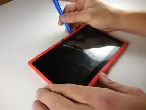
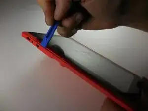
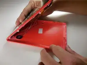
    • First the case must be opened. Insert the blue plastic opening tool where the two casings meet. Pry up until you hear a clip pop and then carefully move around the device. Do this until the front and back casing are completely separate from one another.

    • You will again need to be careful opening the device in order to avoid damaging the speaker, or worse, the motherboard.

    • The clips holding the case together are roughly 1.5 in. apart.

  2. XPT1Iu2fj3pRsrRo
    XPT1Iu2fj3pRsrRo
    RJGUJXInrIqUFpWc
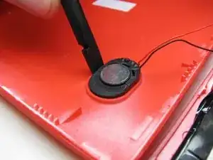
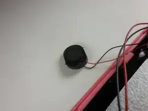
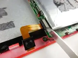
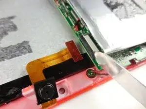
    • Carefully remove the speaker by inserting the spudger between the case and the speaker. Pry upwards until the speaker comes out. Set the speaker to the side.

    • Be careful with the speaker wires. The wires can easily detach from both the speaker and the board.

  3. elxGKQFxP1JUgksC
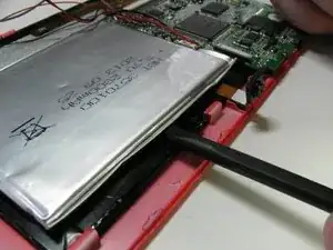
    • Use the spudger to repeatedly gouge between the battery and LCD. Work around the battery until it breaks free.

    • It may feel as though you are pushing extremely hard. This is normal as the adhesive is quite strong. As long as you don't tip the tool you use and puncture the battery / LCD it will be fine.

  4. PXB3fYvfZIu5cBdG
    PXB3fYvfZIu5cBdG
    urOYxertCVuTVAJs
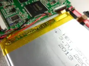
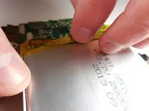
    • The tape around the battery's circuit board is extremely thorough. There are 2 pieces of tape, on folded over the side and another wrapped around the circuit board. Simply peel both off.

  5. FNJJbMhqQUvrlSrp
    FNJJbMhqQUvrlSrp
    x3xGADxxncDF1loL
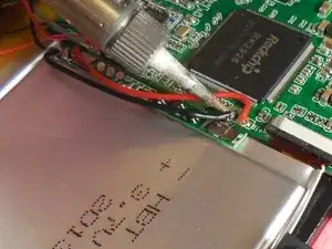
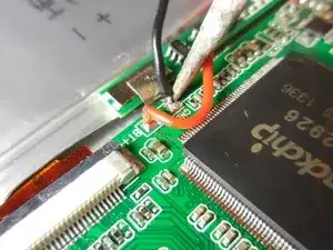
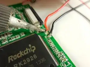
    • Now that the battery is pry'd free and the tape is removed, the wires should be able to move freely. Give yourself as much room as you need, and solder off the connections on the motherboard.

    • How to Solder is iFixit's official guide to use a soldering gun.

  6. BUETUi3d4fhUGWgS
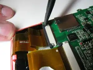
    • Remove the tape from these ribbon cables and their clips.

    • Wires from the speaker may be under the tape and remain stuck to it, care not to disconnect them from the motherboard.

  7. xNwUOiZIcDI2PuxQ
    xNwUOiZIcDI2PuxQ
    JGCBgtXRGa2NxJUG
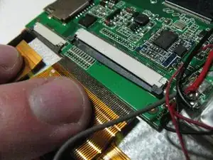
    • Remove the LCD and Digitizer ribbon cables from the motherboard by holding the clips open and pulling the ribbons out.

  8. HqpBdmaDNflRTBqG
    HqpBdmaDNflRTBqG
    4yW5OUntcvpELCHk
    • Remove the Camera Ribbon Cable, by holding the clip open and pulling the camera out.

  9. vueOcZEUerFUNJak
    vueOcZEUerFUNJak
    LNECUwes2PNRx5To
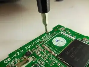
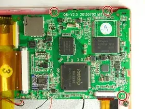
    • Using a screwdriver, unscrew the 3 screws which hold the motherboard on the case.

    • A 3/16 in. Phillips head screw driver will fit the screw heads easily.

    • These are the only three screws in the device and are all the same size.

  10. c3JCZh5avNJHNAkl
    c3JCZh5avNJHNAkl
    ItqPPXN3wBPZRRLc
    kuwebnl33oNTLjOH
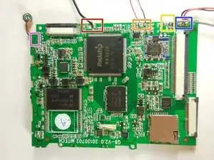
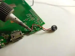
    • You must now use a soldering kit to remove the connections to the motherboard.

    • The battery wires. (If you had not finished this in an earlier step).

    • The Speaker Wires.

    • The Ground.

    • The LCD wires.

    • Finally, the microphone, which lies under the board.

    • How to Solder is iFixit's official guide to use a soldering gun.

Conclusion

To reassemble your device, follow these instructions in reverse order.
Daniel

Member since: 11/03/15

241 Reputation

0 comments