Introduction

  1. TFCqsMnEXfVtFqHT
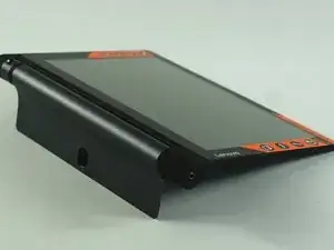
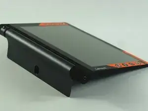
    • Open the built-in kickstand.

  2. Tl2Pfk4toNRLpZ5A
    Tl2Pfk4toNRLpZ5A
    CFbtiXi3pgk6vwtR
    oJdGFSBDZrIXmsXe
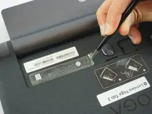
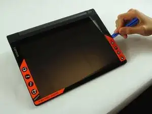
    • Remove the sticker located directly under the the built-in kickstand to reveal two 0.75 mm screws.

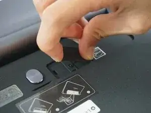
    • Remove the microSD card slot cover. Remove any microSD card (if inserted).

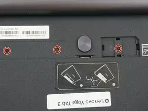
    • Using a Phillips head screwdriver, remove the three 0.75 mm screws.

    On 3 plus model the third screw is not under microSD card but rather under a small sticker on the right side. Plus has longer battery.

    George -

    on the Tab 3 plus , the third screw is not under the sd card but a little further over under another sticker and is painted white

    dan o brien -

  3. yVF45qKSubHrYrZH
    yVF45qKSubHrYrZH
    4RGONwjDhHHduEnv
    UIJQgTfd6e12AOcU
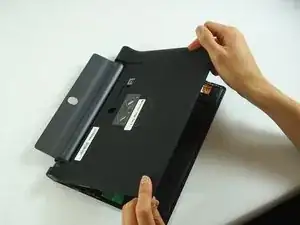
    • Orient the device so the screen is facing you.

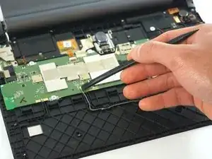
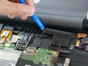
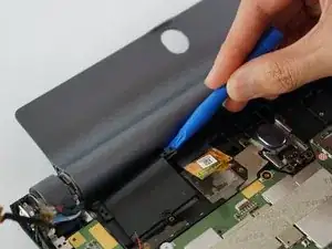
    • Carefully insert the spudger along the seam between the screen and back cover and gently separate the back cover from the device frame.

    • Continue to detach the backplate from the frame by moving the spudger around the perimeter.

    • Some force will be required to detach the small plastic braces securing the backplate to the device.

    On some models there is glue pad under the sim/sdcard tray.

    Ervins Stepanovs -

    Ein Hinweis auf den Federrahmen an der Kamera wäre nützlich. Er ist sehr empfindlich. Ich habe ihn beim Öffnen zerstört und jetzt stellt die Kamera nicht mehr scharf.

    Thomas Spieker -

    Hallo Thomas, tut mir leid, dass deine Kamera nicht mehr schart stellt. Aber die Anleitungen funktionieren wie Wikipedia: Wenn du mehr Infos hast, stelle sie gern allen anderen zur Verfügung!

    Fabian Neidhardt -

    (at least on the Plus model) the most difficult plastic clips are near the micro-SD/SIM. So it is easier to release the other side, where the camera not is. or pull the casing "down" towards the battery/stand.

    Hans Wurst -

  4. rg23BaEexESSguep
    rg23BaEexESSguep
    nXmcvTUvFGRcdnDL
    3vrmaXrascLGBCsl
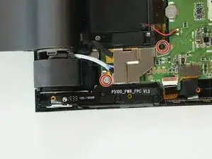
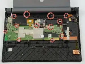
    • Locate the screws in the motherboard the wire cover assembly and the speakers.

    • Use the J000 screwdriver to remove the screws on the motherboard, the wire cover, and the two speakers.

    • Disconnect the wifi connector on the motherboard.

  5. lnOG5CQFWFwheWsi
    lnOG5CQFWFwheWsi
    sGaiaDtYp4yuUJOT
    • Use the spudger to lift the two speakers up from the small adhesive strip.

    • Place the spudger in the upper left corner of the motherboard and lift it to separate it from the adhesive strip under it.

    • Lift away the motherboard.

    Be sure to disconnect all the ribbon cables from the mainboard before lifting it out.

    Bryan Jurish -

Conclusion

To reassemble your device, follow these instructions in reverse order.

Phanudej

Member since: 20/02/17

1184 Reputation

One comment

Dear @phanudej ,

I liked your post. I’d have a remark and a question. I made a mistake during the maintanance; with wich I killed a part of the MOBO. So dear users my advice if you want to connect the LCD connector remove the battery before… I had never this issue but now happened. (the device was switched off)

Could you please take a photo of the powerstage of the LCD (I think it should be that) So between the inductor (100; 10uH coil) and an capacity there is a component I do not know what is it (it smoked away) I assume it is a diode…?! They are in the white rectangle near the LCD connector

Thanks in advance

Best regards
@harrincourt

Jozsef Szlatki -