Introduction
Tools
-
-
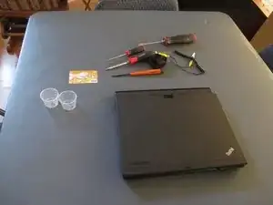
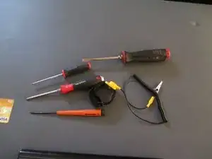
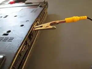
Shown in the pictures are two Philips head screwdriver one is number 0 screwdriver and number 1 screwdriver. Two flat head screwdrivers one a small flat head screwdriver and normal size flat head screwdriver. A standard Anti-static wrist strap and plastic credit card or rewards card. What is not shown is anti-static bag which is shown later.
-
Note: I didn't have ifixit pro tool kit at the time of making this guide.
-
-
-
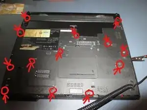
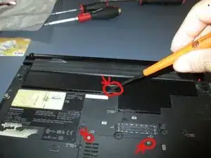
Flip over the bottom of the laptop to find the thirteen Philips head screws. The red circles with the arrows point at where the screws are located. Now take your small flat head screwdriver to push the tab that holds the battery in place. We are removing the battery before we go any further. You can also see the screws that hold the ram cover in.
-
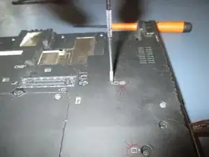
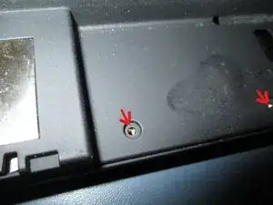
You can see the red circles with arrows showing you what the screw is holding in. Bottom red circle is telling us that it is a chassis screw we need to take out. The top red circle is showing us that it is screw holding in the keyboard along with the chassis.
-
Begin using your number 0 Philips head screwdriver to take out the 13 screws shown earlier.
-
-
-
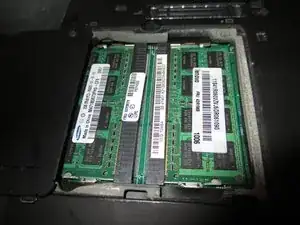
Once you take out all the thirteen screws put them in a container because we don’t want to lose any of them. Try to keep all the bottom screws in the same container so you what screws go where. Now begin to take the two small screws that hold the ram cover in off. Set the ram cover aside and then remove the ram sticks.
-
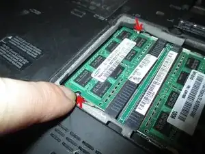
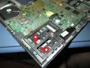
You see with the red arrows there are two tabs that hold in the ram stick. Use both hands to push out the tabs for the ram to pop up. Remove the ram sticks and place them safely somewhere. Please do not stack components on top of each other. This is where I used the anti-static bag.
-
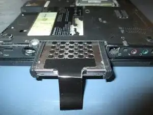
Begin removing the SATA hard drive from the hard drive caddy. It has a small plastic cover that comes off easy. Pull the black tape out this will make it easy for us to pull out the hard drive.
-
-
-
Where the battery was located there is four small screws we need to remove them because those screws hold back chassis piece in place. Set the screws aside for the reassembly.
-
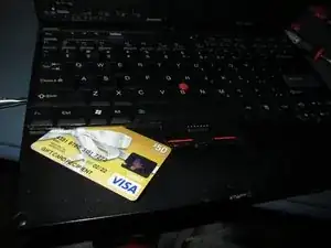
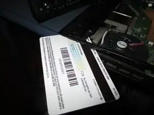
Flip over the laptop to begin front disassembly of the laptop. Take your credit card or small flat head screwdriver slide it underneath the keyboard. What we trying to do pry up gently on the keyboard to remove it.
-
-
-
Once you have the keyboard loose pull up the keyboard so you can see the keyboard cable. Now this keyboard has connector that connects to the Motherboard that just pulls up. Some laptops have ribbon cable that connects to the ribbon cable connector with a tab. Remove the keyboard from the motherboard and set it aside.
-
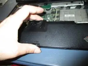
Remove the palm rest by simply pulling up gently on the palm rest and set it aside.
-
-
-
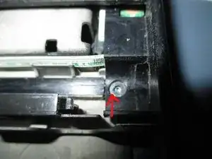
The red arrow shows where a screw is located which holds the back chassis in place. Remove it with your screwdriver and set it in separate container. Since this Lenovo x200 is the tablet model we to swing the LCD screen like in the picture below.
-
This will make it easier for us to remove the chassis plate because the LCD is in the way of removing the chassis plate.Take your credit card slide it underneath the plastic chassis to loosen the plate. Gently lift around the plate with the credit card and now slide the plate out from underneath the LCD screen.
-
-
-
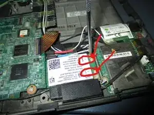
Once the chassis plate is remove let’s focus on removing the Wi-Fi card. To remove the Wi-Fi card, you need to unplug the gray wire and black wire first. Gray wire is connected to the main 1 connection. Black wire is connected to the Aux 2 connection. The picture shows where the wires are connected at
-
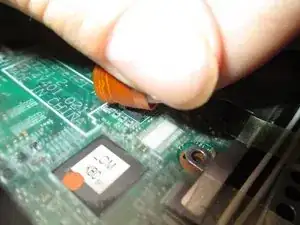
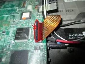
We need undo the ribbon cable that connects the audio ports, USB port and the SD card slot to the Motherboard. How to undo it is using your finger or the small flat head screwdriver to lift on the tab. The reasoning we are undoing the ribbon cable is there are Wi-Fi modules wires underneath it.
-
Those wires are connected to the LCD screen which we will be removing next
-
-
-
There are four screws around the bottom of the LCD screen that we need to remove. Remove all the screws and place them in same container or place.
-
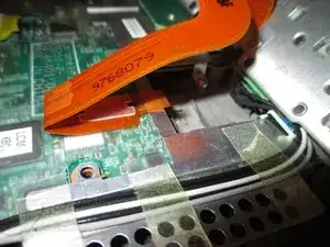
To remove the extension cable card connector from the Motherboard we need to remove the three screws. Remove all three screws from the metal shield and place them with the other LCD screws. Before we remove the extension cable card it would be wise to swing back the LCD in position shown in the picture below.
-
This will make it easier to detach the LCD later..Five screws hold in the extension cable card that connects to the Motherboard. Three small black screws and two small sliver screws. Do not remove the other two small black screws they are attached to extension cable card not need for the removal.
-
Remove the five screws and keep them with the other LCD screws.
-
-
-
It should easily detach from Motherboard by removing the extension cable card that is connected to Motherboard just pull up gently. There is clear tape holding the Wi-Fi cables to the metal shield peel back the tape. Now everything should be loose to lift out the LCD screen.
-
Simply lift out the LCD screen and set it aside for now. Before we move on remove the metal shield underneath the extension cable card.
-
Next, we are going to remove the express card slot screws shown above.
-
-
-
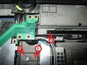
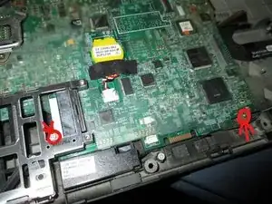
There are two screws shown above that are attached to Motherboard go ahead and remove them. If you have a Bluetooth module installed now would be a good time to remove it. I don’t have a Bluetooth module installed I am skipping this step.
-
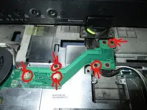
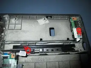
Now we are going to remove Pen switch connector screw and the rear USB hub screw shown in the picture above. Notice long cable coming from the rear USB hub that slides along the channels. The is held with tape or glue it comes off easy when you peel it back. You can disconnect the cable from the bottom if you want.
-
I removed screws instead found it easier to do it this way.
-
-
-
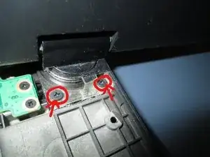
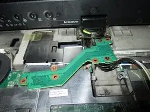
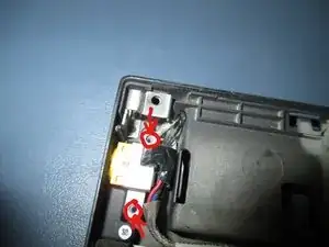
Lastly, we are going to take out the two screws holding the DC-in connector in shown in the picture above. I did not flip over the Motherboard to disconnect DC-in connector nor the fan connector. If I was going to replace the fan or the Motherboard I would have disconnected the connectors.
-
Finally, we are ready to take out our Motherboard. Grab the Motherboard by the express slot try to slide it to right side because if you lift the display port might hit the chassis. y By being gentle you should now be able to remove the entire Motherboard from the chassis.
-
Set the Motherboard on something that will not build up a static charge. I set the Motherboard on the anti-static bag.
-
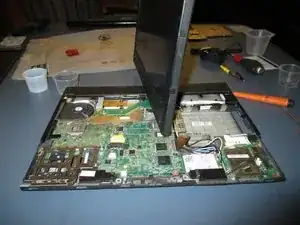
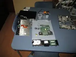
Here is everything disassemble from the chassis shown above. Follow the steps in reverse order to reassemble everything back together. Linked below is references on to properly disassemble your Lenovo Thinkpad x200 tablet https://support.lenovo.com/us/en/solutio...
-
To reassemble your device, follow these instructions in reverse order.
